
Applied Statics and Strength of Materials (6th Edition)
6th Edition
ISBN: 9780133840544
Author: George F. Limbrunner, Craig D'Allaird, Leonard Spiegel
Publisher: PEARSON
expand_more
expand_more
format_list_bulleted
Concept explainers
Videos
Textbook Question
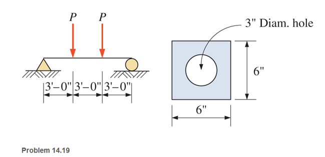
Chapter 14, Problem 14.19P
Calculate the maximum load P that the beam shown can carry based on plastic moment
Expert Solution & Answer
Want to see the full answer?
Check out a sample textbook solution
Students have asked these similar questions
A rectangular bar having width twice the depth is used as a beam. The beam is made of mild steel material having elastic modulus of 2.1 x 10⁵ N/mm? and it
undergoes bending by external load which makes radius of curvature of 150 m.
If the allowable bending stress in the beam is to be limited to 100 MN/m. find the cross section of the beam.
A beam 8 m span is freely supported at its ends and a udl of 40 KN/m is spread over the
whole span of the beam. In addition a concentrated load of 150 KN is applied at a distance of 3
m from the left support. The section of the beam is 200 mm wide and 400 mm deep. Find the
maximum bending stress induced in the beam section.
Q1 A steel beam of I cross-section is simply supported on a span of 4m. Find the safe uniformly distributed load the beam can carry if the tensile stress is not to exceed (60) N/mm2. Also find the maximum compressive stress.
Chapter 14 Solutions
Applied Statics and Strength of Materials (6th Edition)
Ch. 14 - Calculate the section modulus for: (a) a 6 -in-by-...Ch. 14 - Calculate the section modulus (with respect to the...Ch. 14 - Prob. 14.3PCh. 14 - Rework Problem 14.3 changing the orientation of...Ch. 14 - Assume that the timber member (a) of Problem 14.2...Ch. 14 - The structural steel built-up member (b) of...Ch. 14 - A round steel rod, 25 mm in diameter, is subjected...Ch. 14 - A square steel bar, 38 mm on each side, is used as...Ch. 14 - Calculate the moment strength for a W36302...Ch. 14 - Calculate the allowable bending moment for a solid...
Ch. 14 - The beams of cross sections shown are subjected to...Ch. 14 - A solid rectangular simply supported timber beam 6...Ch. 14 - A W1430 supports the loads shown. Calculate the...Ch. 14 - If the allowable shear stress is 100 MPa,...Ch. 14 - A steel pin 112 in diameter is subjected to a...Ch. 14 - A timber power-line pole is 10 in. in diameter at...Ch. 14 - Calculate the value of S and Z and the shape...Ch. 14 - For beams that have cross sections as shown for...Ch. 14 - Calculate the maximum load P that the beam shown...Ch. 14 - A 412 (S4S) hem-fir timber beam carries a...Ch. 14 - A simply supported W1636 A992 steel beam carries a...Ch. 14 - A W250115 steel wide-flange section supports a...Ch. 14 - Assume that the floor joist dimensions of Example...Ch. 14 - Calculate the allowable superimposed uniformly...Ch. 14 - A 3 -in.-by- 12 -in. (S4S) scaffold timber plank...Ch. 14 - For the following computer problems, any...Ch. 14 - For the following computer problems, any...Ch. 14 - For the following computer problems, any...Ch. 14 - Calculate the section modulus with respect to the...Ch. 14 - The timber box section (a) of Problem 14.29 is...Ch. 14 - A timber beam is subjected to a maximum bending...Ch. 14 - Rework Problem 14.31 assuming that the beam is...Ch. 14 - A 12 -in.-diameter steel rod projects 2 ft...Ch. 14 - Calculate the maximum bending stress in a W530101...Ch. 14 - A cantilever cast-iron beam is 6 ft long and has a...Ch. 14 - 14.36 Calculate the moment strength for a...Ch. 14 - A W813 steel wide-flange beam on a 20 -ft span is...Ch. 14 - A simply supported beam with a cruciform cross...Ch. 14 - A rectangular beam 100 mm in width and 250 mm in...Ch. 14 - The timber box section (a) of Problem 14.29 is...Ch. 14 - For the I-shaped timber beam shown, calculate the...Ch. 14 - 14.42 A steel wide-flange beam is oriented so that...Ch. 14 - A W1045steel wide-flange beam supports a uniformly...Ch. 14 - 14.44 A steel wide-flange section is subjected to...Ch. 14 - A W30108 steel wide-flange beam is simply...Ch. 14 - A W612 is strengthened with a 34 -in.-by- 34 -in....Ch. 14 - Four wood boards 1 in. by 6 in. in cross section...Ch. 14 - A lintel consists of two 8 -in.-by- 12 in. steel...Ch. 14 - A 50 -mm-by- 300 -mm scaffold timber plank, placed...Ch. 14 - A laminated wood beam is built up by gluing...Ch. 14 - A rectangular hollow shape carries loads as shown....Ch. 14 - For the beam shown, calculate the maximum tensile...Ch. 14 - 14.53 A box beam is built up of four -in.-by--in....Ch. 14 - 14.54 Find the value of the loads P that can be...Ch. 14 - 14.55 Solve Problem 14.54 assuming that the timber...Ch. 14 - Calculate the values of S and Z and the shape...Ch. 14 - 14.57 A is supported on simple supports on a -ft...
Knowledge Booster


Learn more about
Need a deep-dive on the concept behind this application? Look no further. Learn more about this topic, mechanical-engineering and related others by exploring similar questions and additional content below.Similar questions
- Draw diagrams of shear force and bending moment for beam and loading shown. Calculate the maximum tensile and compressive stresses in the beam. X=407 N/m Y=2.21 m Z=51,4 mmarrow_forwardFind the maximum stress in the beam if it is fixed at the left end,free at the right end subjected to a uniform distributed load of200 lb/in.arrow_forwardCompute the maximum bending moment, maxi- mum deflection and the maximum bending stress for a railroad rail subjected to a single wheel load of 100 kN. The foundation modulus k = 15 MN / m². Assume that I = 400 × 10-8 m², E = 200 GN/m², the depth of the rail is 180 mm and that the distance of the centroidal axis of the cross-section of the rail from the top surface is 100 mm.arrow_forward
- For the beam shown, there is a roller at 1.5 feet from the left and a pinned support at the far-right end. Two loads are applied: a 450-kip vertical load and a 15 kip*ft moment. The cross-sectional shape of the beam is shown on the right. What is the maximum stress on this beam? Note: A kip is a kilopound.arrow_forwardA cantilever beam of cross-section 90 mm. width 120 mm deep carries a UDL of 12 KN/m. over the entire length and a concentrated load of 15 KN at the right end. Find the bending stress in the beam, when the length of beam is 10 m.arrow_forwardA overhang beam hanged at B(6m) has two loads of 8 & 4 kn at 6 and 9 m. Calulate its moment using castigliano's theorem. Also calculate Strain Energy.arrow_forward
- For the beam shown below, Find the bending stress at point A. 16 50 kN 3 m. 3 marrow_forwardGive me right solution according to the question. Draw the shear force diagram and Bending moment diagrams for the beam clearly.. Take M= 60 KN-m P=30 KNarrow_forwardThe simple beam shown carries a uniform load w, = 10 kN/m. The dimensions a, b, c, and d are 0.6 m, 0.4 m, 50 mm and 80 mm, respectively. What will be the maximum vertical shear stress in the beam in MPa? d aarrow_forward
- 3. Two beams are supported as shown in the diagram below, each 150mm x 200mm x 6 meters. Beam CD is a cantilever beam carrying a uniformly distributed load of 6 KN/m freely supported on beam AB. Beam AB is freely supported on each ends. E = 13.8 GPa for both beam. Neglect the weight of the beam. a. Compute the reaction at D. b. Compute the deflection at D. c. Compute the bending stress of beam CD. 6 ka lm бт 6m 6marrow_forwardFind the maximum bending compressive stress in psi, caused by the load P=1100 lbsarrow_forwardFor the beam shown below, determine the maximum bending stress in the beam. sketch thesection stress distribution.arrow_forward
arrow_back_ios
SEE MORE QUESTIONS
arrow_forward_ios
Recommended textbooks for you
 Elements Of ElectromagneticsMechanical EngineeringISBN:9780190698614Author:Sadiku, Matthew N. O.Publisher:Oxford University Press
 Mechanics of Materials (10th Edition)Mechanical EngineeringISBN:9780134319650Author:Russell C. HibbelerPublisher:PEARSON
 Thermodynamics: An Engineering ApproachMechanical EngineeringISBN:9781259822674Author:Yunus A. Cengel Dr., Michael A. BolesPublisher:McGraw-Hill Education
 Control Systems EngineeringMechanical EngineeringISBN:9781118170519Author:Norman S. NisePublisher:WILEY
 Mechanics of Materials (MindTap Course List)Mechanical EngineeringISBN:9781337093347Author:Barry J. Goodno, James M. GerePublisher:Cengage Learning
 Engineering Mechanics: StaticsMechanical EngineeringISBN:9781118807330Author:James L. Meriam, L. G. Kraige, J. N. BoltonPublisher:WILEY
Elements Of Electromagnetics
Mechanical Engineering
ISBN:9780190698614
Author:Sadiku, Matthew N. O.
Publisher:Oxford University Press
Mechanics of Materials (10th Edition)
Mechanical Engineering
ISBN:9780134319650
Author:Russell C. Hibbeler
Publisher:PEARSON
Thermodynamics: An Engineering Approach
Mechanical Engineering
ISBN:9781259822674
Author:Yunus A. Cengel Dr., Michael A. Boles
Publisher:McGraw-Hill Education
Control Systems Engineering
Mechanical Engineering
ISBN:9781118170519
Author:Norman S. Nise
Publisher:WILEY
Mechanics of Materials (MindTap Course List)
Mechanical Engineering
ISBN:9781337093347
Author:Barry J. Goodno, James M. Gere
Publisher:Cengage Learning
Engineering Mechanics: Statics
Mechanical Engineering
ISBN:9781118807330
Author:James L. Meriam, L. G. Kraige, J. N. Bolton
Publisher:WILEY
Everything About COMBINED LOADING in 10 Minutes! Mechanics of Materials; Author: Less Boring Lectures;https://www.youtube.com/watch?v=N-PlI900hSg;License: Standard youtube license