
Applied Statics and Strength of Materials (6th Edition)
6th Edition
ISBN: 9780133840544
Author: George F. Limbrunner, Craig D'Allaird, Leonard Spiegel
Publisher: PEARSON
expand_more
expand_more
format_list_bulleted
Concept explainers
Videos
Textbook Question
Chapter 14, Problem 14.11P
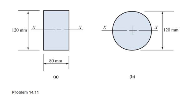
The beams of cross sections shown are subjected to a total shear force of
Expert Solution & Answer

Learn your wayIncludes step-by-step video

schedule04:34
Students have asked these similar questions
3-55 A multifluid container is connected to a U-tube,
as shown in Fig. P3–55. For the given specific gravities
and fluid column heights, determine the gage pressure at
A. Also determine the height of a mercury column that
would create the same pressure at A. Answers: 0.415 kPa,
0.311 cm
I need help answering parts a and b
Required information
Water initially at 200 kPa and 300°C is contained in a piston-cylinder device fitted with stops. The water is allowed to cool
at constant pressure until it exists as a saturated vapor and the piston rests on the stops. Then the water continues to cool
until the pressure is 100 kPa.
NOTE: This is a multi-part question. Once an answer is submitted, you will be unable to return to this part.
Water
200 kPa
300°C
On the T-V diagram, sketch, with respect to the saturation lines, the process curves passing through the initial, intermediate, and final states of the water. Label the
T, P, and V values for end states on the process curves.
Please upload your response/solution by using the controls provided below.
Chapter 14 Solutions
Applied Statics and Strength of Materials (6th Edition)
Ch. 14 - Calculate the section modulus for: (a) a 6 -in-by-...Ch. 14 - Calculate the section modulus (with respect to the...Ch. 14 - Prob. 14.3PCh. 14 - Rework Problem 14.3 changing the orientation of...Ch. 14 - Assume that the timber member (a) of Problem 14.2...Ch. 14 - The structural steel built-up member (b) of...Ch. 14 - A round steel rod, 25 mm in diameter, is subjected...Ch. 14 - A square steel bar, 38 mm on each side, is used as...Ch. 14 - Calculate the moment strength for a W36302...Ch. 14 - Calculate the allowable bending moment for a solid...
Ch. 14 - The beams of cross sections shown are subjected to...Ch. 14 - A solid rectangular simply supported timber beam 6...Ch. 14 - A W1430 supports the loads shown. Calculate the...Ch. 14 - If the allowable shear stress is 100 MPa,...Ch. 14 - A steel pin 112 in diameter is subjected to a...Ch. 14 - A timber power-line pole is 10 in. in diameter at...Ch. 14 - Calculate the value of S and Z and the shape...Ch. 14 - For beams that have cross sections as shown for...Ch. 14 - Calculate the maximum load P that the beam shown...Ch. 14 - A 412 (S4S) hem-fir timber beam carries a...Ch. 14 - A simply supported W1636 A992 steel beam carries a...Ch. 14 - A W250115 steel wide-flange section supports a...Ch. 14 - Assume that the floor joist dimensions of Example...Ch. 14 - Calculate the allowable superimposed uniformly...Ch. 14 - A 3 -in.-by- 12 -in. (S4S) scaffold timber plank...Ch. 14 - For the following computer problems, any...Ch. 14 - For the following computer problems, any...Ch. 14 - For the following computer problems, any...Ch. 14 - Calculate the section modulus with respect to the...Ch. 14 - The timber box section (a) of Problem 14.29 is...Ch. 14 - A timber beam is subjected to a maximum bending...Ch. 14 - Rework Problem 14.31 assuming that the beam is...Ch. 14 - A 12 -in.-diameter steel rod projects 2 ft...Ch. 14 - Calculate the maximum bending stress in a W530101...Ch. 14 - A cantilever cast-iron beam is 6 ft long and has a...Ch. 14 - 14.36 Calculate the moment strength for a...Ch. 14 - A W813 steel wide-flange beam on a 20 -ft span is...Ch. 14 - A simply supported beam with a cruciform cross...Ch. 14 - A rectangular beam 100 mm in width and 250 mm in...Ch. 14 - The timber box section (a) of Problem 14.29 is...Ch. 14 - For the I-shaped timber beam shown, calculate the...Ch. 14 - 14.42 A steel wide-flange beam is oriented so that...Ch. 14 - A W1045steel wide-flange beam supports a uniformly...Ch. 14 - 14.44 A steel wide-flange section is subjected to...Ch. 14 - A W30108 steel wide-flange beam is simply...Ch. 14 - A W612 is strengthened with a 34 -in.-by- 34 -in....Ch. 14 - Four wood boards 1 in. by 6 in. in cross section...Ch. 14 - A lintel consists of two 8 -in.-by- 12 in. steel...Ch. 14 - A 50 -mm-by- 300 -mm scaffold timber plank, placed...Ch. 14 - A laminated wood beam is built up by gluing...Ch. 14 - A rectangular hollow shape carries loads as shown....Ch. 14 - For the beam shown, calculate the maximum tensile...Ch. 14 - 14.53 A box beam is built up of four -in.-by--in....Ch. 14 - 14.54 Find the value of the loads P that can be...Ch. 14 - 14.55 Solve Problem 14.54 assuming that the timber...Ch. 14 - Calculate the values of S and Z and the shape...Ch. 14 - 14.57 A is supported on simple supports on a -ft...
Additional Engineering Textbook Solutions
Find more solutions based on key concepts
Which technologies that were imagined by George Orwell (Eric Blair) in his novel 1984 have become reality? Are ...
Computer Science: An Overview (13th Edition) (What's New in Computer Science)
ICA 8-37
An ideal gas in a 1.25-gailon [gal] container is at a temperature of 125 degrees Celsius [°C] and pres...
Thinking Like an Engineer: An Active Learning Approach (4th Edition)
For the circuit shown, use the node-voltage method to find v1, v2, and i1.
How much power is delivered to the c...
Electric Circuits. (11th Edition)
Repeat Programming Project 18 from Chapter 4, but use a method that displays a circular disk as a subtask. Grap...
Java: An Introduction to Problem Solving and Programming (8th Edition)
What is the importance of modeling in engineering? How are the mathematical models for engineering processes pr...
HEAT+MASS TRANSFER:FUND.+APPL.
Write an iterative version of the function defined in Self-Test Exercise 2.
Problem Solving with C++ (10th Edition)
Knowledge Booster


Learn more about
Need a deep-dive on the concept behind this application? Look no further. Learn more about this topic, mechanical-engineering and related others by exploring similar questions and additional content below.Similar questions
- A piston-cylinder device contains 0.87 kg of refrigerant-134a at -10°C. The piston that is free to move has a mass of 12 kg and a diameter of 25 cm. The local atmospheric pressure is 88 kPa. Now, heat is transferred to refrigerant-134a until the temperature is 15°C. Use data from the tables. R-134a -10°C Determine the change in the volume of the cylinder of the refrigerant-134a if the specific volume and enthalpy of R-134a at the initial state of 90.4 kPa and -10°C and at the final state of 90.4 kPa and 15°C are as follows: = 0.2418 m³/kg, h₁ = 247.77 kJ/kg 3 v2 = 0.2670 m³/kg, and h₂ = 268.18 kJ/kg The change in the volume of the cylinder is marrow_forwardA piston-cylinder device contains 0.87 kg of refrigerant-134a at -10°C. The piston that is free to move has a mass of 12 kg and a diameter of 25 cm. The local atmospheric pressure is 88 kPa. Now, heat is transferred to refrigerant-134a until the temperature is 15°C. Use data from the tables. R-134a -10°C Determine the final pressure of the refrigerant-134a. The final pressure is kPa.arrow_forwardThe hydraulic cylinder BC exerts on member AB a force P directed along line BC. The force P must have a 560-N component perpendicular to member AB. A M 45° 30° C Determine the force component along line AB. The force component along line AB is N.arrow_forward
- ! Required information A telephone cable is clamped at A to the pole AB. The tension in the left-hand portion of the cable is given to be T₁ = 815 lb. A 15° 25° B T₂ Using trigonometry, determine the required tension T₂ in the right-hand portion if the resultant R of the forces exerted by the cable at A is to be vertical. The required tension is lb.arrow_forwardWhat are examples of at least three (3) applications of tolerance fitting analysis.arrow_forwardThe primary material used in the production of glass products is silica sand. True or Falsearrow_forward
- Which one of the following is the most common polymer type in fiber-reinforced polymer composites? thermosets thermoplastics elastomers none of the abovearrow_forwardA pattern for a product is larger than the actual finished part. True or Falsearrow_forwardIn the lost foam process, the pattern doesn’t need to be removed from the mold. True or Falsearrow_forward
- Tempering eliminates internal stresses in glass. True or Falsearrow_forwardThermoset polymers can be recycled with little to no degradation in properties. True or Falsearrow_forwardTwo forces are applied as shown to a hook support. The magnitude of P is 38 N. 50 N 25° DG a 터 Using trigonometry, determine the required angle a such that the resultant R of the two forces applied to the support will be horizontal. The value of a isarrow_forward
arrow_back_ios
SEE MORE QUESTIONS
arrow_forward_ios
Recommended textbooks for you
 Elements Of ElectromagneticsMechanical EngineeringISBN:9780190698614Author:Sadiku, Matthew N. O.Publisher:Oxford University Press
 Mechanics of Materials (10th Edition)Mechanical EngineeringISBN:9780134319650Author:Russell C. HibbelerPublisher:PEARSON
 Thermodynamics: An Engineering ApproachMechanical EngineeringISBN:9781259822674Author:Yunus A. Cengel Dr., Michael A. BolesPublisher:McGraw-Hill Education
 Control Systems EngineeringMechanical EngineeringISBN:9781118170519Author:Norman S. NisePublisher:WILEY
 Mechanics of Materials (MindTap Course List)Mechanical EngineeringISBN:9781337093347Author:Barry J. Goodno, James M. GerePublisher:Cengage Learning
 Engineering Mechanics: StaticsMechanical EngineeringISBN:9781118807330Author:James L. Meriam, L. G. Kraige, J. N. BoltonPublisher:WILEY
Elements Of Electromagnetics
Mechanical Engineering
ISBN:9780190698614
Author:Sadiku, Matthew N. O.
Publisher:Oxford University Press
Mechanics of Materials (10th Edition)
Mechanical Engineering
ISBN:9780134319650
Author:Russell C. Hibbeler
Publisher:PEARSON
Thermodynamics: An Engineering Approach
Mechanical Engineering
ISBN:9781259822674
Author:Yunus A. Cengel Dr., Michael A. Boles
Publisher:McGraw-Hill Education
Control Systems Engineering
Mechanical Engineering
ISBN:9781118170519
Author:Norman S. Nise
Publisher:WILEY
Mechanics of Materials (MindTap Course List)
Mechanical Engineering
ISBN:9781337093347
Author:Barry J. Goodno, James M. Gere
Publisher:Cengage Learning
Engineering Mechanics: Statics
Mechanical Engineering
ISBN:9781118807330
Author:James L. Meriam, L. G. Kraige, J. N. Bolton
Publisher:WILEY
Understanding Shear Force and Bending Moment Diagrams; Author: The Efficient Engineer;https://www.youtube.com/watch?v=C-FEVzI8oe8;License: Standard YouTube License, CC-BY
Bending Stress; Author: moodlemech;https://www.youtube.com/watch?v=9QIqewkE6xM;License: Standard Youtube License