
Mechanics of Materials (10th Edition)
10th Edition
ISBN: 9780134319650
Author: Russell C. Hibbeler
Publisher: PEARSON
expand_more
expand_more
format_list_bulleted
Concept explainers
Videos
Textbook Question
Chapter 13.5, Problem 13.62P
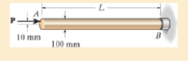
The brass rod is fixed at one end and free at the other end. If the length of the rod is L = 2 m, determine the greatest allowable load P that can be applied so that the rod does not buckle or yield. Also, determine the largest sidesway deflection of the rod due to the loading. Etr = 101 GPa, σY = 69 MPa.
Expert Solution & Answer
Want to see the full answer?
Check out a sample textbook solution
Students have asked these similar questions
Problem 6. The circular plate shown rotates about its vertical diameter. At the instant shown, the
angular velocity ₁ of the plate is 10 rad/s and is decreasing at the rate of 25 rad/s². The disk lies
in the XY plane and Point D of strap CD moves upward. The relative speed u of Point D of strap
CD is 1.5 m/s and is decreasing at the rate of 3 m/s².
Determine (a) the velocity of D, (b) the acceleration of D.
Answers: =0.75 +1.299]-1.732k m/s a=-28.6 +3.03-10.67k m/s²
200 mm
x
Z
Problem 1. The flywheel A has an angular velocity o 5 rad/s. Link AB is connected via ball
and socket joints to the flywheel at A and a slider at B. Find the angular velocity of link AB and
the velocity of slider B at this instant. (Partial Answer: @ABN = -2î + 2.25; red
Z
-1.2 ft
C
-7 Y
-1.5 ft-
B
2.0 ft
Need help please
Chapter 13 Solutions
Mechanics of Materials (10th Edition)
Ch. 13.3 - A 50-in long steel rod has a diameter of 1 in....Ch. 13.3 - A 12-ft wooden rectangular column has the...Ch. 13.3 - The A992 steel column can be considered pinned at...Ch. 13.3 - A steel pipe is fixed supported at its ends. If it...Ch. 13.3 - Determine the maximum force P that can be...Ch. 13.3 - The A992 steel rod BC has a diameter of 50 mm and...Ch. 13.3 - Determine the critical buckling load for the...Ch. 13.3 - The column consists of a rigid member that is...Ch. 13.3 - The aircraft link is made from an A992 steel rod....Ch. 13.3 - Rigid bars AB and BC are pin connected at B. If...
Ch. 13.3 - A 2014-T6 aluminium alloy column has a length of 6...Ch. 13.3 - Solve Prob. 13-5 if the column is pinned at its...Ch. 13.3 - The W12 50 is made of A992 steel and is used as a...Ch. 13.3 - The W12 50 is made of A992 steel and is used as a...Ch. 13.3 - A steel column has a length of 9 m and is fixed at...Ch. 13.3 - A steel column has a length of 9 m and is pinned...Ch. 13.3 - The A992 steel angle has a cross-sectional area of...Ch. 13.3 - The 50-mm-diameter C86100 bronze rod is fixed...Ch. 13.3 - Determine the maximum load P the frame can support...Ch. 13.3 - The W8 67 wide-flange A-36 steel column can be...Ch. 13.3 - Prob. 13.15PCh. 13.3 - Prob. 13.16PCh. 13.3 - The 10-ft wooden rectangular column has the...Ch. 13.3 - The 10-fl wooden column has the dimensions shown....Ch. 13.3 - Determine the maximum force P that can be applied...Ch. 13.3 - The A-36 steel pipe has an outer diameter of 2 in....Ch. 13.3 - The A-36 steel pipe has an outer diameter of 2 in....Ch. 13.3 - The deck is supported by the two 40-mm-square...Ch. 13.3 - The deck is supported by the two 40-mm-square...Ch. 13.3 - The beam is supported by the three pin-connected...Ch. 13.3 - The W14 30 A992 steel column is assumed pinned at...Ch. 13.3 - The A992 steel bar AB has a square cross section....Ch. 13.3 - The linkage is made using two A992 steel rods,...Ch. 13.3 - The linkage is made using two A992 steel rods,...Ch. 13.3 - The linkage is made using two A-36 steel rods,...Ch. 13.3 - The linkage is made using two A-36 steel rods,...Ch. 13.3 - The steel bar AB has a rectangular cross section....Ch. 13.3 - Determine if the frame can support a load of P =...Ch. 13.3 - Determine the maximum allowable load P that can be...Ch. 13.3 - Prob. 13.34PCh. 13.3 - Prob. 13.35PCh. 13.3 - The members of the truss are assumed to be pin...Ch. 13.3 - Solve Prob. 1336 for member AB, which has a radius...Ch. 13.3 - The truss is made from A992 steel bars, each of...Ch. 13.3 - The truss is made from A992 steel bars, each of...Ch. 13.3 - Prob. 13.40PCh. 13.3 - The ideal column has a weight w (force/length) and...Ch. 13.3 - The ideal column is subjected to the force F at...Ch. 13.3 - The column with constant El has the end...Ch. 13.3 - Consider an ideal column as in Fig.13-10 c, having...Ch. 13.3 - Consider an ideal column as in Fig. 13-10d, having...Ch. 13.5 - The wood column is fixed at its base and free at...Ch. 13.5 - The W10 12 structural A-36 steel column is used...Ch. 13.5 - The W10 12 structural A-36 steel column is used...Ch. 13.5 - The aluminium column is fixed at the bottom and...Ch. 13.5 - Prob. 13.50PCh. 13.5 - Prob. 13.51PCh. 13.5 - The aluminum rod is fixed at its base and free and...Ch. 13.5 - Assume that the wood column is pin connected at...Ch. 13.5 - Prob. 13.54PCh. 13.5 - The wood column is pinned at its base and top. If...Ch. 13.5 - Prob. 13.56PCh. 13.5 - Prob. 13.57PCh. 13.5 - Prob. 13.58PCh. 13.5 - Prob. 13.59PCh. 13.5 - The wood column is pinned at its base and top. If...Ch. 13.5 - The brass rod is fixed at one end and free at the...Ch. 13.5 - The brass rod is fixed at one end and free at the...Ch. 13.5 - Prob. 13.63PCh. 13.5 - A W14 30 structural A-36 steel column is pin...Ch. 13.5 - Prob. 13.65PCh. 13.5 - The 6061-T6 aluminum alloy solid shaft is fixed at...Ch. 13.5 - The 6061-T6 aluminum alloy solid shaft is fixed at...Ch. 13.5 - The W14 53 structural A992 steel column is fixed...Ch. 13.5 - The W14 53 column is fixed at its base and free...Ch. 13.5 - Prob. 13.70PCh. 13.5 - The stress-strain diagram for a material can be...Ch. 13.5 - The stress-strain diagram for a material can be...Ch. 13.5 - The stress-strain diagram for the material of a...Ch. 13.5 - Construct the buckling curve, P/A versus L/ r, for...Ch. 13.5 - The stress-strain diagram of the material can be...Ch. 13.5 - The stress-strain diagram of the material can be...Ch. 13.5 - Prob. 13.77PCh. 13.6 - Determine the largest length of a W10 12...Ch. 13.6 - Using the AISC equations, select from AppendixB...Ch. 13.6 - Take Y = 50 ksi.Ch. 13.6 - Determine the longest length of a W8 31...Ch. 13.6 - Using the AISC equations, select from AppendixB...Ch. 13.6 - Prob. 13.83PCh. 13.6 - Using the AISC equations, select from AppendixB...Ch. 13.6 - Prob. 13.85PCh. 13.6 - Prob. 13.86PCh. 13.6 - Prob. 13.87PCh. 13.6 - Prob. 13.88PCh. 13.6 - Using the AISC equations, check if a column having...Ch. 13.6 - The beam and column arrangement is used in a...Ch. 13.6 - Prob. 13.91PCh. 13.6 - Prob. 13.92PCh. 13.6 - The 1-in.-diameter rod is used to support an axial...Ch. 13.6 - The 1-in.-diameter rod is used to support an axial...Ch. 13.6 - Prob. 13.95PCh. 13.6 - Prob. 13.96PCh. 13.6 - Prob. 13.97PCh. 13.6 - Prob. 13.98PCh. 13.6 - The tube is 0.25 in. thick, is made of 2014-T6...Ch. 13.6 - Prob. 13.100PCh. 13.6 - A rectangular wooden column has the cross section...Ch. 13.6 - Prob. 13.102PCh. 13.6 - Prob. 13.103PCh. 13.6 - The bar is made of aluminum alloy 2014-T6....Ch. 13.6 - Prob. 13.105PCh. 13.6 - Prob. 13.106PCh. 13.7 - The W8 15 wide-flange A-36 steel column is...Ch. 13.7 - Solve Prob.13-107 if the column is fixed at its...Ch. 13.7 - Prob. 13.109PCh. 13.7 - Prob. 13.110PCh. 13.7 - The W8 15 wide-flange A992 steel column is fixed...Ch. 13.7 - The W8 15 wide-flange A992 steel column is fixed...Ch. 13.7 - The W12 22 wide-flange A-36 steel column is fixed...Ch. 13.7 - Prob. 13.114PCh. 13.7 - Prob. 13.115PCh. 13.7 - Prob. 13.116PCh. 13.7 - A 20-ft-long column is made of aluminum alloy...Ch. 13.7 - A 20-ft-long column is made of aluminum alloy...Ch. 13.7 - The 2014-T6 aluminum hollow column is fixed at its...Ch. 13.7 - The 2014-T6 aluminum hollow column is fixed at its...Ch. 13.7 - Prob. 13.121PCh. 13.7 - Prob. 13.122PCh. 13.7 - Prob. 13.123PCh. 13.7 - Prob. 13.124PCh. 13.7 - The 10-in.-diameter utility pole supports the...Ch. 13.7 - Using the NFPA equations of Sec 13.6. and Eq....Ch. 13.7 - Prob. 13.127PCh. 13 - The wood column has a thickness of 4 in. and a...Ch. 13 - The wood column has a thickness of 4 in. and a...Ch. 13 - A steel column has a length of 5 m and is free at...Ch. 13 - The square structural A992 steel tubing has outer...Ch. 13 - If the A-36 steel solid circular rod BD has a...Ch. 13 - If P = 15 kip, determine the required minimum...Ch. 13 - The steel pipe is fixed supported at its ends. If...Ch. 13 - The W200 46 wide-flange A992-steel column can be...Ch. 13 - The wide-flange A992 steel column has the cross...Ch. 13 - The wide-flange A992 steel column has the cross...
Knowledge Booster


Learn more about
Need a deep-dive on the concept behind this application? Look no further. Learn more about this topic, mechanical-engineering and related others by exploring similar questions and additional content below.Similar questions
- PROBLEM 15.225 The bent rod shown rotates at the constant rate @₁ = 5 rad/s and collar C moves toward point B at a constant relative speed u = 39 in./s. Knowing that collar C is halfway between points B and D at the instant shown, determine its velocity and acceleration. Answers: v=-45 +36.6)-31.2 k in./s āc = -2911-270} in./s² 6 in 20.8 in. 14.4 in.arrow_forwardNeed help, please show all work, steps, units and please box out and round answers to 3 significant figures. Thank you!..arrow_forwardNeed help, please show all work, steps, units and please box out and round answers to 3 significant figures. Thank you!...arrow_forward
- FL y b C Z Determine the moment about O due to the force F shown, the magnitude of the force F = 76.0 lbs. Note: Pay attention to the axis. Values for dimensions on the figure are given in the following table. Note the figure may not be to scale. Variable Value a 1.90 ft b 2.80 ft с 2.60 ft d 2.30 ft Mo 144 ft-lb = -212 × 1 + xk) ☑+212arrow_forward20 in. PROBLEM 15.206 Rod AB is connected by ball-and-socket joints to collar A and to the 16-in.-diameter disk C. Knowing that disk C rotates counterclockwise at the constant rate ₁ =3 rad/s in the zx plane, determine the velocity of collar A for the position shown. 25 in. B 8 in. Answer: -30 in/s =arrow_forwardB Z 001 2.5 ft PROBLEM 15.236 The arm AB of length 16 ft is used to provide an elevated platform for construction workers. In the position shown, arm AB is being raised at the constant rate de/dt = 0.25 rad/s; simultaneously, the unit is being rotated about the Y axis at the constant rate ₁ =0.15 rad/s. Knowing that 20°, determine the velocity and acceleration of Point B. Answers: 1.371 +3.76)+1.88k ft/s a=1.22 -0.342)-0.410k ft/s² Xarrow_forward
- F1 3 5 4 P F2 F2 Ꮎ Ꮎ b P 3 4 5 F1 The electric pole is subject to the forces shown. Force F1 245 N and force F2 = 310 N with an angle = 20.2°. Determine the moment about point P of all forces. Take counterclockwise moments to be positive. = Values for dimensions on the figure are given in the following table. Note the figure may not be to scale. Variable Value a 2.50 m b 11.3 m C 13.0 m The moment about point P is 3,414 m. × N- If the moment about point P sums up to be zero. Determine the distance c while all other values remained the same. 1.26 m.arrow_forwardZ 0.2 m B PROBLEM 15.224 Rod AB is welded to the 0.3-m-radius plate, which rotates at the constant rate ₁ = 6 rad/s. Knowing that collar D moves toward end B of the rod at a constant speed u = 1.3 m, determine, for the position shown, (a) the velocity of D, (b) the acceleration of D. Answers: 1.2 +0.5-1.2k m/s a=-7.21-14.4k m/s² A 0.25 m 0.3 marrow_forwardI am trying to code in MATLAB the equations of motion for malankovich orbitlal elements. But, I am having a problem with the B matrix. Since f matrix is 7x1 and a_d matrix has to be 3x1, the B matrix has to be 7x3. I don't know how that is possible. Can you break down the B matrix for me and let me know what size it is?arrow_forward
- I am trying to code the solution to the problem in the image in MATLAB. I wanted to know what is the milankovich constraint equation that is talked about in part b.arrow_forwardmylabmastering.pearson.com Chapter 12 - Lecture Notes.pptx: (MAE 272-01) (SP25) DY... P Pearson MyLab and Mastering Scoresarrow_forwardAir modeled as an ideal gas enters an insulated compressor at a temperature of 300 K and 100 kPa, and leaves at 600 kPa. The mass flowrate of air entering the compressor is 50 kg/hr, and the power consumed by the compressor is 3 kW. (Rair = 0.287 kJ/kg-K, k = 1.4, cp = 1.0045 kJ/kg-K, cv = 0.718 kJ/kg-K) Determine the isentropic exit temperature (Te,s) of the air in [K]. Determine the actual exit temperature (Te) of the air in [K]. Determine the isentropic efficiency of the compressor. (Answer: ηc,s = 93.3%) Determine the rate of entropy generated through the compressor in [kW/K]. (Answer: Ṡgen = 0.000397 kW/K)arrow_forwardarrow_back_iosSEE MORE QUESTIONSarrow_forward_ios
Recommended textbooks for you
 Elements Of ElectromagneticsMechanical EngineeringISBN:9780190698614Author:Sadiku, Matthew N. O.Publisher:Oxford University Press
 Mechanics of Materials (10th Edition)Mechanical EngineeringISBN:9780134319650Author:Russell C. HibbelerPublisher:PEARSON
 Thermodynamics: An Engineering ApproachMechanical EngineeringISBN:9781259822674Author:Yunus A. Cengel Dr., Michael A. BolesPublisher:McGraw-Hill Education
 Control Systems EngineeringMechanical EngineeringISBN:9781118170519Author:Norman S. NisePublisher:WILEY
 Mechanics of Materials (MindTap Course List)Mechanical EngineeringISBN:9781337093347Author:Barry J. Goodno, James M. GerePublisher:Cengage Learning
 Engineering Mechanics: StaticsMechanical EngineeringISBN:9781118807330Author:James L. Meriam, L. G. Kraige, J. N. BoltonPublisher:WILEY
Elements Of Electromagnetics
Mechanical Engineering
ISBN:9780190698614
Author:Sadiku, Matthew N. O.
Publisher:Oxford University Press
Mechanics of Materials (10th Edition)
Mechanical Engineering
ISBN:9780134319650
Author:Russell C. Hibbeler
Publisher:PEARSON
Thermodynamics: An Engineering Approach
Mechanical Engineering
ISBN:9781259822674
Author:Yunus A. Cengel Dr., Michael A. Boles
Publisher:McGraw-Hill Education
Control Systems Engineering
Mechanical Engineering
ISBN:9781118170519
Author:Norman S. Nise
Publisher:WILEY
Mechanics of Materials (MindTap Course List)
Mechanical Engineering
ISBN:9781337093347
Author:Barry J. Goodno, James M. Gere
Publisher:Cengage Learning
Engineering Mechanics: Statics
Mechanical Engineering
ISBN:9781118807330
Author:James L. Meriam, L. G. Kraige, J. N. Bolton
Publisher:WILEY
EVERYTHING on Axial Loading Normal Stress in 10 MINUTES - Mechanics of Materials; Author: Less Boring Lectures;https://www.youtube.com/watch?v=jQ-fNqZWrNg;License: Standard YouTube License, CC-BY