
Mechanics of Materials (10th Edition)
10th Edition
ISBN: 9780134319650
Author: Russell C. Hibbeler
Publisher: PEARSON
expand_more
expand_more
format_list_bulleted
Concept explainers
Videos
Textbook Question
Chapter 13.3, Problem 13.8P
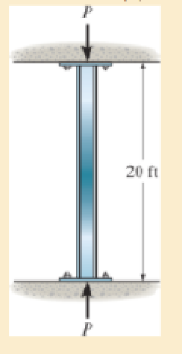
The W12 × 50 is made of A992 steel and is used as a column that has a length of 20 ft. If the ends of the column are fixed supported, can the column support the critical load without yielding?
Expert Solution & Answer
Want to see the full answer?
Check out a sample textbook solution
Students have asked these similar questions
=
The forces F₁ = 590 lb, F₂ = 380 lb, F3 = 240 lb and F
330 lb. Determine the forces in each member of the truss.
Use positive values to indicate tension and negative values to
indicate compression.
a
a
a
D
b
F₁
A
000
B.
779977
F₂V
H
G
E
F4
b
BY NC SA
2013 Michael Swanbom
Values for dimensions on the figure are given in the following
table. Note the figure may not be to scale.
Variable Value
a
6 ft
b
10.1 ft
The force in member AB is
lb.
The force in member AH is
lb.
The force in member GH is
lb.
The force in member BH is
lb.
The force in member BC is
lb.
The force in member BG is
lb.
The force in member EG is
lb.
The force in member CD is
lb.
The force in member DE is
lb.
The force in member CE is
lb.
The force in member CG is
lb.
Multiple Choice
Circle the best answer to each statement.
1. Which type of surface deviation is controlled by a cy-
lindricity tolerance but not by a circularity tolerance?
A.
B.
C.
Ovality
Taper
Lobing
D. None of the above
2. When verifying a cylindricity tolerance, the inspec-
tion method must be able to collect a set of points and
determine the:
A. Distance between two coaxial cylinders that con-
tain the set of points
B.
Cylinder that circumscribes the set of points
C. Cylinder that inscribes the set of points
D.
Distance between two coaxial circles that contain
the set of points
3. Where Rule #1 applies to a cylindrical regular feature
of size, the tolerance value of a cylindricity tolerance
applied to the feature of size must be
tolerance.
A. Less than
B. Equal to
C. Greater than
D. None of the above
the size
4. Which of the following modifiers may be applied with
a cylindricity tolerance?
A. M
B.
C. ℗
D. Ø
5. Which geometric tolerance can provide an indirect
cylindricity…
The beam AB is attached to the wall in the xz plane by a
fixed support at A. A force of
F = (−129î + 69.0ĵ + 3591) N is applied to the end of
the beam at B. The weight of the beam can be modeled with
a uniform distributed load of intensity w = 85.0 N/m acting in
the negative z direction along its entire length. Find the
support reactions at A.
Z
с
A
b
a
B
F
y
Cc 10
BY NC SA
2016 Eric Davishahl
X
Values for dimensions on the figure are given in the following.
table. Note the figure may not be to scale.
Variable
Value
a
5.60 m
b
5.00 m
C
3.70 m
A
II
=
MA = (
m
2.>
~.>
+
+
k) N
k) N-
Chapter 13 Solutions
Mechanics of Materials (10th Edition)
Ch. 13.3 - A 50-in long steel rod has a diameter of 1 in....Ch. 13.3 - A 12-ft wooden rectangular column has the...Ch. 13.3 - The A992 steel column can be considered pinned at...Ch. 13.3 - A steel pipe is fixed supported at its ends. If it...Ch. 13.3 - Determine the maximum force P that can be...Ch. 13.3 - The A992 steel rod BC has a diameter of 50 mm and...Ch. 13.3 - Determine the critical buckling load for the...Ch. 13.3 - The column consists of a rigid member that is...Ch. 13.3 - The aircraft link is made from an A992 steel rod....Ch. 13.3 - Rigid bars AB and BC are pin connected at B. If...
Ch. 13.3 - A 2014-T6 aluminium alloy column has a length of 6...Ch. 13.3 - Solve Prob. 13-5 if the column is pinned at its...Ch. 13.3 - The W12 50 is made of A992 steel and is used as a...Ch. 13.3 - The W12 50 is made of A992 steel and is used as a...Ch. 13.3 - A steel column has a length of 9 m and is fixed at...Ch. 13.3 - A steel column has a length of 9 m and is pinned...Ch. 13.3 - The A992 steel angle has a cross-sectional area of...Ch. 13.3 - The 50-mm-diameter C86100 bronze rod is fixed...Ch. 13.3 - Determine the maximum load P the frame can support...Ch. 13.3 - The W8 67 wide-flange A-36 steel column can be...Ch. 13.3 - Prob. 13.15PCh. 13.3 - Prob. 13.16PCh. 13.3 - The 10-ft wooden rectangular column has the...Ch. 13.3 - The 10-fl wooden column has the dimensions shown....Ch. 13.3 - Determine the maximum force P that can be applied...Ch. 13.3 - The A-36 steel pipe has an outer diameter of 2 in....Ch. 13.3 - The A-36 steel pipe has an outer diameter of 2 in....Ch. 13.3 - The deck is supported by the two 40-mm-square...Ch. 13.3 - The deck is supported by the two 40-mm-square...Ch. 13.3 - The beam is supported by the three pin-connected...Ch. 13.3 - The W14 30 A992 steel column is assumed pinned at...Ch. 13.3 - The A992 steel bar AB has a square cross section....Ch. 13.3 - The linkage is made using two A992 steel rods,...Ch. 13.3 - The linkage is made using two A992 steel rods,...Ch. 13.3 - The linkage is made using two A-36 steel rods,...Ch. 13.3 - The linkage is made using two A-36 steel rods,...Ch. 13.3 - The steel bar AB has a rectangular cross section....Ch. 13.3 - Determine if the frame can support a load of P =...Ch. 13.3 - Determine the maximum allowable load P that can be...Ch. 13.3 - Prob. 13.34PCh. 13.3 - Prob. 13.35PCh. 13.3 - The members of the truss are assumed to be pin...Ch. 13.3 - Solve Prob. 1336 for member AB, which has a radius...Ch. 13.3 - The truss is made from A992 steel bars, each of...Ch. 13.3 - The truss is made from A992 steel bars, each of...Ch. 13.3 - Prob. 13.40PCh. 13.3 - The ideal column has a weight w (force/length) and...Ch. 13.3 - The ideal column is subjected to the force F at...Ch. 13.3 - The column with constant El has the end...Ch. 13.3 - Consider an ideal column as in Fig.13-10 c, having...Ch. 13.3 - Consider an ideal column as in Fig. 13-10d, having...Ch. 13.5 - The wood column is fixed at its base and free at...Ch. 13.5 - The W10 12 structural A-36 steel column is used...Ch. 13.5 - The W10 12 structural A-36 steel column is used...Ch. 13.5 - The aluminium column is fixed at the bottom and...Ch. 13.5 - Prob. 13.50PCh. 13.5 - Prob. 13.51PCh. 13.5 - The aluminum rod is fixed at its base and free and...Ch. 13.5 - Assume that the wood column is pin connected at...Ch. 13.5 - Prob. 13.54PCh. 13.5 - The wood column is pinned at its base and top. If...Ch. 13.5 - Prob. 13.56PCh. 13.5 - Prob. 13.57PCh. 13.5 - Prob. 13.58PCh. 13.5 - Prob. 13.59PCh. 13.5 - The wood column is pinned at its base and top. If...Ch. 13.5 - The brass rod is fixed at one end and free at the...Ch. 13.5 - The brass rod is fixed at one end and free at the...Ch. 13.5 - Prob. 13.63PCh. 13.5 - A W14 30 structural A-36 steel column is pin...Ch. 13.5 - Prob. 13.65PCh. 13.5 - The 6061-T6 aluminum alloy solid shaft is fixed at...Ch. 13.5 - The 6061-T6 aluminum alloy solid shaft is fixed at...Ch. 13.5 - The W14 53 structural A992 steel column is fixed...Ch. 13.5 - The W14 53 column is fixed at its base and free...Ch. 13.5 - Prob. 13.70PCh. 13.5 - The stress-strain diagram for a material can be...Ch. 13.5 - The stress-strain diagram for a material can be...Ch. 13.5 - The stress-strain diagram for the material of a...Ch. 13.5 - Construct the buckling curve, P/A versus L/ r, for...Ch. 13.5 - The stress-strain diagram of the material can be...Ch. 13.5 - The stress-strain diagram of the material can be...Ch. 13.5 - Prob. 13.77PCh. 13.6 - Determine the largest length of a W10 12...Ch. 13.6 - Using the AISC equations, select from AppendixB...Ch. 13.6 - Take Y = 50 ksi.Ch. 13.6 - Determine the longest length of a W8 31...Ch. 13.6 - Using the AISC equations, select from AppendixB...Ch. 13.6 - Prob. 13.83PCh. 13.6 - Using the AISC equations, select from AppendixB...Ch. 13.6 - Prob. 13.85PCh. 13.6 - Prob. 13.86PCh. 13.6 - Prob. 13.87PCh. 13.6 - Prob. 13.88PCh. 13.6 - Using the AISC equations, check if a column having...Ch. 13.6 - The beam and column arrangement is used in a...Ch. 13.6 - Prob. 13.91PCh. 13.6 - Prob. 13.92PCh. 13.6 - The 1-in.-diameter rod is used to support an axial...Ch. 13.6 - The 1-in.-diameter rod is used to support an axial...Ch. 13.6 - Prob. 13.95PCh. 13.6 - Prob. 13.96PCh. 13.6 - Prob. 13.97PCh. 13.6 - Prob. 13.98PCh. 13.6 - The tube is 0.25 in. thick, is made of 2014-T6...Ch. 13.6 - Prob. 13.100PCh. 13.6 - A rectangular wooden column has the cross section...Ch. 13.6 - Prob. 13.102PCh. 13.6 - Prob. 13.103PCh. 13.6 - The bar is made of aluminum alloy 2014-T6....Ch. 13.6 - Prob. 13.105PCh. 13.6 - Prob. 13.106PCh. 13.7 - The W8 15 wide-flange A-36 steel column is...Ch. 13.7 - Solve Prob.13-107 if the column is fixed at its...Ch. 13.7 - Prob. 13.109PCh. 13.7 - Prob. 13.110PCh. 13.7 - The W8 15 wide-flange A992 steel column is fixed...Ch. 13.7 - The W8 15 wide-flange A992 steel column is fixed...Ch. 13.7 - The W12 22 wide-flange A-36 steel column is fixed...Ch. 13.7 - Prob. 13.114PCh. 13.7 - Prob. 13.115PCh. 13.7 - Prob. 13.116PCh. 13.7 - A 20-ft-long column is made of aluminum alloy...Ch. 13.7 - A 20-ft-long column is made of aluminum alloy...Ch. 13.7 - The 2014-T6 aluminum hollow column is fixed at its...Ch. 13.7 - The 2014-T6 aluminum hollow column is fixed at its...Ch. 13.7 - Prob. 13.121PCh. 13.7 - Prob. 13.122PCh. 13.7 - Prob. 13.123PCh. 13.7 - Prob. 13.124PCh. 13.7 - The 10-in.-diameter utility pole supports the...Ch. 13.7 - Using the NFPA equations of Sec 13.6. and Eq....Ch. 13.7 - Prob. 13.127PCh. 13 - The wood column has a thickness of 4 in. and a...Ch. 13 - The wood column has a thickness of 4 in. and a...Ch. 13 - A steel column has a length of 5 m and is free at...Ch. 13 - The square structural A992 steel tubing has outer...Ch. 13 - If the A-36 steel solid circular rod BD has a...Ch. 13 - If P = 15 kip, determine the required minimum...Ch. 13 - The steel pipe is fixed supported at its ends. If...Ch. 13 - The W200 46 wide-flange A992-steel column can be...Ch. 13 - The wide-flange A992 steel column has the cross...Ch. 13 - The wide-flange A992 steel column has the cross...
Knowledge Booster


Learn more about
Need a deep-dive on the concept behind this application? Look no further. Learn more about this topic, mechanical-engineering and related others by exploring similar questions and additional content below.Similar questions
- need help?arrow_forwardA bent pipe is attached to a wall with brackets as shown. A force of F = 180 lb is applied to the end of the tube with direction indicated by the dimensions in the figure. Determine the support reactions at the brackets B, C, and D. Model these brackets as journal bearings (only force reactions perpendicular to the axis of the tube) and neglect couple moment reactions. Assume the distance between the supports at B and C and the tube bends nearby are negligible such that the support at C is directly above the support at D and the dimension g gives the distance between supports B and C. Enter your answers in Cartesian components. 2013 Michael Swanbom cc 10 BY NC SA g h א B 8° У A C x каж Values for dimensions on the figure are given in the table below. Note the figure may not be to scale. Variable Value a 6.72 in b 11.8 in с 14.8 in d 42.0 in h 26.6 in g 28.0 in → The reaction at B is B = lb. The reaction at C is C = lb. The reaction at D is D = lb. + << + + 2. + + 557 〈んarrow_forwardThe force F1 = 10 kN, F2 = 10 kN, F3 = 10 kN, F4 = 5 KN are acting on the sttructure shown. Determine the forces in the members specified below. Use positive values to indicate tension and negative values to indicate compression. F2 D b F1 F3 C E b F4 b B F a G Values for dimensions on the figure are given in the following table. Note the figure may not be to scale. Variable Value a 3 m b 4 m The force in member BC is KN. The force in member BE is KN. The force in member EF is KN.arrow_forward
- h = The transmission tower is subjected to the forces F₁ 3.6 KN at 50° and F2 = 3.3 kN at = 35°. Determine the forces in members BC, BP, PQ, PC, CD, DP and NP. Use positive values to indicate tension and negative values to indicate compression. 不 кажаж в *а*аж E N M d d IF, c B CENTER LINE S อ K F₂ Kbb cc 10 BY NC SA 2013 Michael Swanbom Values for dimensions on the figure are given in the following table. Note the figure may not be to scale. Variable Value a 1.7 m b 4.9 m с 3 m d 5.2 m h 8.4 m Values for dimensions on the figure are given in the following table. Note the figure may not be to scale. Variable Value a 1.7 m 4.9 m с 3 m d 5.2 m h 8.4 m The force in member BC is KN. The force in member BP is KN. The force in member PQ is KN. The force in member PC is KN. The force in member CD is KN. The force in member DP is KN. The force in member NP is KN.arrow_forwardنصاف Sheet Asteel bar of rectangular cross section with dimension Shown in fig. below. This bar is as Connected toawell. Using welded Join a long the sides als only find the weld size (h). Where: Tall = 35 MN/M² F=213.30 answer/h= 4.04 ☐ Yomm Soomm 100mmarrow_forwardFEAarrow_forward
- FEAarrow_forwardHELP?arrow_forwardTrue and False Indicate if each statement is true or false. T/F 1. Rule #1 protects the function of assembly. T/F 2. One of the fundamental dimensioning rules requires all dimensions apply in the free-state condition for rigid parts. T/F 3. The fundamental dimensioning rules that apply on a drawing must be listed in the general notes. T/F 4. Where Rule #1 applies to a drawing, it limits the form of every feature of size on the drawing. T/F 5. Rule #1 limits the variation between features of size on a part. T/F 6. The designer must specify on the drawing which features of size use Rule #1. T/F T/F T/F 7. Rule #1 applies to nonrigid parts (in the unrestrained state). 8. A GO gage is a fixed-limit gage. 9. Rule #1 requires that the form of an individual regular feature of size is controlled by its limits of sizearrow_forward
arrow_back_ios
SEE MORE QUESTIONS
arrow_forward_ios
Recommended textbooks for you
 Mechanics of Materials (MindTap Course List)Mechanical EngineeringISBN:9781337093347Author:Barry J. Goodno, James M. GerePublisher:Cengage Learning
Mechanics of Materials (MindTap Course List)
Mechanical Engineering
ISBN:9781337093347
Author:Barry J. Goodno, James M. Gere
Publisher:Cengage Learning
Column buckling; Author: Amber Book;https://www.youtube.com/watch?v=AvvaCi_Nn94;License: Standard Youtube License