
Mechanics of Materials (10th Edition)
10th Edition
ISBN: 9780134319650
Author: Russell C. Hibbeler
Publisher: PEARSON
expand_more
expand_more
format_list_bulleted
Concept explainers
Videos
Textbook Question
Chapter 13, Problem 13.8RP
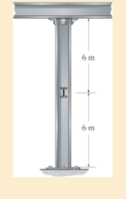
The W200 × 46 wide-flange A992-steel column can be considered pinned at its top and fixed at its base. Also, the column is braced at its mid-height against weak axis buckling. Determine the maximum axial load the column can support without causing it to buckle.
R13−8
Expert Solution & Answer
Want to see the full answer?
Check out a sample textbook solution
Students have asked these similar questions
dny
dn-1y
dn-1u
dn-24
+a1
+
+ Any
=
bi
+b₂-
+ +bnu.
dtn
dtn-1
dtn-1
dtn-2
a) Let be a root of the characteristic equation
1
sn+a1sn-
+
+an
= : 0.
Show that if u(t) = 0, the differential equation has the solution y(t) = e\t.
b) Let к be a zero of the polynomial
b(s) = b₁s-1+b2sn−2+
Show that if the input is u(t)
equation that is identically zero.
=
..
+bn.
ekt, then there is a solution to the differential
B
60 ft
WAB
AB
30%
:
The crane's telescopic boom rotates with the angular velocity w = 0.06 rad/s and
angular acceleration a = 0.07 rad/s². At the same instant, the boom is extending
with a constant speed of 0.8 ft/s, measured relative to the boom. Determine the
magnitude of the acceleration of point B at this instant.
The motion of peg P is constrained by the lemniscate curved
slot in OB and by the slotted arm OA. (Figure 1)
If OA rotates counterclockwise with a constant angular velocity of 0 = 3 rad/s, determine the magnitude of the velocity of peg P at 0 = 30°.
Express your answer to three significant figures and include the appropriate units.
Determine the magnitude of the acceleration of peg P at 0 = 30°.
Express your answer to three significant figures and include the appropriate units.
0
(4 cos 2 0)m²
B
A
Chapter 13 Solutions
Mechanics of Materials (10th Edition)
Ch. 13.3 - A 50-in long steel rod has a diameter of 1 in....Ch. 13.3 - A 12-ft wooden rectangular column has the...Ch. 13.3 - The A992 steel column can be considered pinned at...Ch. 13.3 - A steel pipe is fixed supported at its ends. If it...Ch. 13.3 - Determine the maximum force P that can be...Ch. 13.3 - The A992 steel rod BC has a diameter of 50 mm and...Ch. 13.3 - Determine the critical buckling load for the...Ch. 13.3 - The column consists of a rigid member that is...Ch. 13.3 - The aircraft link is made from an A992 steel rod....Ch. 13.3 - Rigid bars AB and BC are pin connected at B. If...
Ch. 13.3 - A 2014-T6 aluminium alloy column has a length of 6...Ch. 13.3 - Solve Prob. 13-5 if the column is pinned at its...Ch. 13.3 - The W12 50 is made of A992 steel and is used as a...Ch. 13.3 - The W12 50 is made of A992 steel and is used as a...Ch. 13.3 - A steel column has a length of 9 m and is fixed at...Ch. 13.3 - A steel column has a length of 9 m and is pinned...Ch. 13.3 - The A992 steel angle has a cross-sectional area of...Ch. 13.3 - The 50-mm-diameter C86100 bronze rod is fixed...Ch. 13.3 - Determine the maximum load P the frame can support...Ch. 13.3 - The W8 67 wide-flange A-36 steel column can be...Ch. 13.3 - Prob. 13.15PCh. 13.3 - Prob. 13.16PCh. 13.3 - The 10-ft wooden rectangular column has the...Ch. 13.3 - The 10-fl wooden column has the dimensions shown....Ch. 13.3 - Determine the maximum force P that can be applied...Ch. 13.3 - The A-36 steel pipe has an outer diameter of 2 in....Ch. 13.3 - The A-36 steel pipe has an outer diameter of 2 in....Ch. 13.3 - The deck is supported by the two 40-mm-square...Ch. 13.3 - The deck is supported by the two 40-mm-square...Ch. 13.3 - The beam is supported by the three pin-connected...Ch. 13.3 - The W14 30 A992 steel column is assumed pinned at...Ch. 13.3 - The A992 steel bar AB has a square cross section....Ch. 13.3 - The linkage is made using two A992 steel rods,...Ch. 13.3 - The linkage is made using two A992 steel rods,...Ch. 13.3 - The linkage is made using two A-36 steel rods,...Ch. 13.3 - The linkage is made using two A-36 steel rods,...Ch. 13.3 - The steel bar AB has a rectangular cross section....Ch. 13.3 - Determine if the frame can support a load of P =...Ch. 13.3 - Determine the maximum allowable load P that can be...Ch. 13.3 - Prob. 13.34PCh. 13.3 - Prob. 13.35PCh. 13.3 - The members of the truss are assumed to be pin...Ch. 13.3 - Solve Prob. 1336 for member AB, which has a radius...Ch. 13.3 - The truss is made from A992 steel bars, each of...Ch. 13.3 - The truss is made from A992 steel bars, each of...Ch. 13.3 - Prob. 13.40PCh. 13.3 - The ideal column has a weight w (force/length) and...Ch. 13.3 - The ideal column is subjected to the force F at...Ch. 13.3 - The column with constant El has the end...Ch. 13.3 - Consider an ideal column as in Fig.13-10 c, having...Ch. 13.3 - Consider an ideal column as in Fig. 13-10d, having...Ch. 13.5 - The wood column is fixed at its base and free at...Ch. 13.5 - The W10 12 structural A-36 steel column is used...Ch. 13.5 - The W10 12 structural A-36 steel column is used...Ch. 13.5 - The aluminium column is fixed at the bottom and...Ch. 13.5 - Prob. 13.50PCh. 13.5 - Prob. 13.51PCh. 13.5 - The aluminum rod is fixed at its base and free and...Ch. 13.5 - Assume that the wood column is pin connected at...Ch. 13.5 - Prob. 13.54PCh. 13.5 - The wood column is pinned at its base and top. If...Ch. 13.5 - Prob. 13.56PCh. 13.5 - Prob. 13.57PCh. 13.5 - Prob. 13.58PCh. 13.5 - Prob. 13.59PCh. 13.5 - The wood column is pinned at its base and top. If...Ch. 13.5 - The brass rod is fixed at one end and free at the...Ch. 13.5 - The brass rod is fixed at one end and free at the...Ch. 13.5 - Prob. 13.63PCh. 13.5 - A W14 30 structural A-36 steel column is pin...Ch. 13.5 - Prob. 13.65PCh. 13.5 - The 6061-T6 aluminum alloy solid shaft is fixed at...Ch. 13.5 - The 6061-T6 aluminum alloy solid shaft is fixed at...Ch. 13.5 - The W14 53 structural A992 steel column is fixed...Ch. 13.5 - The W14 53 column is fixed at its base and free...Ch. 13.5 - Prob. 13.70PCh. 13.5 - The stress-strain diagram for a material can be...Ch. 13.5 - The stress-strain diagram for a material can be...Ch. 13.5 - The stress-strain diagram for the material of a...Ch. 13.5 - Construct the buckling curve, P/A versus L/ r, for...Ch. 13.5 - The stress-strain diagram of the material can be...Ch. 13.5 - The stress-strain diagram of the material can be...Ch. 13.5 - Prob. 13.77PCh. 13.6 - Determine the largest length of a W10 12...Ch. 13.6 - Using the AISC equations, select from AppendixB...Ch. 13.6 - Take Y = 50 ksi.Ch. 13.6 - Determine the longest length of a W8 31...Ch. 13.6 - Using the AISC equations, select from AppendixB...Ch. 13.6 - Prob. 13.83PCh. 13.6 - Using the AISC equations, select from AppendixB...Ch. 13.6 - Prob. 13.85PCh. 13.6 - Prob. 13.86PCh. 13.6 - Prob. 13.87PCh. 13.6 - Prob. 13.88PCh. 13.6 - Using the AISC equations, check if a column having...Ch. 13.6 - The beam and column arrangement is used in a...Ch. 13.6 - Prob. 13.91PCh. 13.6 - Prob. 13.92PCh. 13.6 - The 1-in.-diameter rod is used to support an axial...Ch. 13.6 - The 1-in.-diameter rod is used to support an axial...Ch. 13.6 - Prob. 13.95PCh. 13.6 - Prob. 13.96PCh. 13.6 - Prob. 13.97PCh. 13.6 - Prob. 13.98PCh. 13.6 - The tube is 0.25 in. thick, is made of 2014-T6...Ch. 13.6 - Prob. 13.100PCh. 13.6 - A rectangular wooden column has the cross section...Ch. 13.6 - Prob. 13.102PCh. 13.6 - Prob. 13.103PCh. 13.6 - The bar is made of aluminum alloy 2014-T6....Ch. 13.6 - Prob. 13.105PCh. 13.6 - Prob. 13.106PCh. 13.7 - The W8 15 wide-flange A-36 steel column is...Ch. 13.7 - Solve Prob.13-107 if the column is fixed at its...Ch. 13.7 - Prob. 13.109PCh. 13.7 - Prob. 13.110PCh. 13.7 - The W8 15 wide-flange A992 steel column is fixed...Ch. 13.7 - The W8 15 wide-flange A992 steel column is fixed...Ch. 13.7 - The W12 22 wide-flange A-36 steel column is fixed...Ch. 13.7 - Prob. 13.114PCh. 13.7 - Prob. 13.115PCh. 13.7 - Prob. 13.116PCh. 13.7 - A 20-ft-long column is made of aluminum alloy...Ch. 13.7 - A 20-ft-long column is made of aluminum alloy...Ch. 13.7 - The 2014-T6 aluminum hollow column is fixed at its...Ch. 13.7 - The 2014-T6 aluminum hollow column is fixed at its...Ch. 13.7 - Prob. 13.121PCh. 13.7 - Prob. 13.122PCh. 13.7 - Prob. 13.123PCh. 13.7 - Prob. 13.124PCh. 13.7 - The 10-in.-diameter utility pole supports the...Ch. 13.7 - Using the NFPA equations of Sec 13.6. and Eq....Ch. 13.7 - Prob. 13.127PCh. 13 - The wood column has a thickness of 4 in. and a...Ch. 13 - The wood column has a thickness of 4 in. and a...Ch. 13 - A steel column has a length of 5 m and is free at...Ch. 13 - The square structural A992 steel tubing has outer...Ch. 13 - If the A-36 steel solid circular rod BD has a...Ch. 13 - If P = 15 kip, determine the required minimum...Ch. 13 - The steel pipe is fixed supported at its ends. If...Ch. 13 - The W200 46 wide-flange A992-steel column can be...Ch. 13 - The wide-flange A992 steel column has the cross...Ch. 13 - The wide-flange A992 steel column has the cross...
Additional Engineering Textbook Solutions
Find more solutions based on key concepts
A nozzle at A discharges water with an initial velocity of 36 ft/s at an angle with the horizontal. Determine ...
Vector Mechanics For Engineers
17–1C A high-speed aircraft is cruising in still air. How does the temperature of air at the nose of the aircra...
Thermodynamics: An Engineering Approach
How are relationships between tables expressed in a relational database?
Modern Database Management
Assume a telephone signal travels through a cable at two-thirds the speed of light. How long does it take the s...
Electric Circuits. (11th Edition)
The following C++ program will not compile because the lines have been mixed up. cout Success\n; cout Success...
Starting Out with C++ from Control Structures to Objects (9th Edition)
Knowledge Booster


Learn more about
Need a deep-dive on the concept behind this application? Look no further. Learn more about this topic, mechanical-engineering and related others by exploring similar questions and additional content below.Similar questions
- 5: The structure shown was designed to support a30-kN load. It consists of a boom AB with a 30 x 50-mmrectangular cross section and a rod BC with a 20-mm-diametercircular cross section. The boom and the rod are connected bya pin at B and are supported by pins and brackets at A and C,respectively.1. Calculate the normal stress in boom AB and rod BC,indicate if in tension or compression.2. Calculate the shear stress of pins at A, B and C.3. Calculate the bearing stresses at A in member AB,and in the bracket.arrow_forward4: The boom AC is a 4-in. square steel tube with a wallthickness of 0.25 in. The boom is supported by the 0.5-in.-diameter pinat A, and the 0.375-in.-diameter cable BC. The working stresses are 25ksi for the cable, 18 ksi for the boom, and 13.6 ksi for shear in the pin.Neglect the weight of the boom.1. Calculate the maximum value of P (kips) based on boom compression and the maximum value of P (kips) based on tension in the cable.2. Calculate the maximum value of P (kips) based on shear in pin.arrow_forward3: A steel strut S serving as a brace for a boat hoist transmits a compressive force P = 54 kN to the deck of a pier as shown in Fig. STR-08. The strut has a hollow square cross section with a wall thickness t =12mm and the angle θ between the strut and the horizontal is 40°. A pin through the strut transmits the compressive force from the strut to two gusset plates G that are welded to the base plate B. Four anchor bolts fasten the base plate to the deck. The diameter of the pin is 20mm, the thickness of the gusset plates is 16mm, the thickness of the base plate is 8mm, and the diameter of the anchor bolts is 12mm. Disregard any friction between the base plate and the deck.1. Determine the shear stress in the pin, in MPa and the shear stress in the anchor bolts, in MPa.2. Determine the bearing stress in the strut holes, in MPa.arrow_forward
- 1. In the figure, the beam, W410x67, with 9 mm web thicknesssubjects the girder, W530x109 with 12 mm web thickness to a shear load,P (kN). 2L – 90 mm × 90 mm × 6 mm with bolts frame the beam to thegirder.Given: S1 = S2 = S5 = 40 mm; S3 = 75 mm; S4 = 110 mmAllowable Stresses are as follows:Bolt shear stress, Fv = 125 MPaBolt bearing stress, Fp = 510 MPa1. Determine the allowable load, P (kN), based on the shearcapacity of the 4 – 25 mm diameter bolts (4 – d1) and calculate the allowable load, P (kN), based on bolt bearing stress on the web of the beam.2. If P = 450 kN, determine the minimum diameter (mm) of 4 – d1based on allowable bolt shear stress and bearing stress of thebeam web.arrow_forward6: The 6-kN load P is supported by two wooden members of 75 x 125-mm uniform cross section that are joined by the simple glued scarf splice shown.1. Calculate the normal stress in the glue, in MPa.2. Calculate the shear stress in the glue, in MPa.arrow_forwardUsing Matlab calculate the following performance characteristics for a Tesla Model S undergoing the 4506 drive cycle test Prated Trated Ebat 80kW 254 Nm 85kWh/1645kg MUEH A rwheel 0.315M 133.3 C 0.491 Ng ng 7g 8.190.315 8.19 0.315 7ed= 85% Ebpt 35-956 DRIVE AXLE Ebfb chę =85% V Minverter H/A Battery Charger En AC Pry 9) required energy output from the motor to drive this cycle Cassume no regenerative braking) b) range of the Tesla Model S for this drive cycle (assume no regenerative breaking c) estimated mpge cycle of the Tesla Model S for this drive Cassume no regenerative breaking) d) Recalculate parts abc now assuming you can regenerate returns correctly due to inefficiency. from braking. Be careful to handle the diminishing energy braking makes in terms of required e) Quantify the percentage difference that regenerative required energy, range and mpge, DI L Ta a ra OLarrow_forward
- HW.5.1 Determine the vertical displacement of joint C on the truss as shown by using Castigliano's theorem. Let E = 200(109) GPa and A = 300 mm² 4 m E 20 kN 3 m 3 m B D 30 kN Carrow_forward3-55 A multifluid container is connected to a U-tube, as shown in Fig. P3–55. For the given specific gravities and fluid column heights, determine the gage pressure at A. Also determine the height of a mercury column that would create the same pressure at A. Answers: 0.415 kPa, 0.311 cmarrow_forwardI need help answering parts a and barrow_forward
- Required information Water initially at 200 kPa and 300°C is contained in a piston-cylinder device fitted with stops. The water is allowed to cool at constant pressure until it exists as a saturated vapor and the piston rests on the stops. Then the water continues to cool until the pressure is 100 kPa. NOTE: This is a multi-part question. Once an answer is submitted, you will be unable to return to this part. Water 200 kPa 300°C On the T-V diagram, sketch, with respect to the saturation lines, the process curves passing through the initial, intermediate, and final states of the water. Label the T, P, and V values for end states on the process curves. Please upload your response/solution by using the controls provided below.arrow_forwardA piston-cylinder device contains 0.87 kg of refrigerant-134a at -10°C. The piston that is free to move has a mass of 12 kg and a diameter of 25 cm. The local atmospheric pressure is 88 kPa. Now, heat is transferred to refrigerant-134a until the temperature is 15°C. Use data from the tables. R-134a -10°C Determine the change in the volume of the cylinder of the refrigerant-134a if the specific volume and enthalpy of R-134a at the initial state of 90.4 kPa and -10°C and at the final state of 90.4 kPa and 15°C are as follows: = 0.2418 m³/kg, h₁ = 247.77 kJ/kg 3 v2 = 0.2670 m³/kg, and h₂ = 268.18 kJ/kg The change in the volume of the cylinder is marrow_forwardA piston-cylinder device contains 0.87 kg of refrigerant-134a at -10°C. The piston that is free to move has a mass of 12 kg and a diameter of 25 cm. The local atmospheric pressure is 88 kPa. Now, heat is transferred to refrigerant-134a until the temperature is 15°C. Use data from the tables. R-134a -10°C Determine the final pressure of the refrigerant-134a. The final pressure is kPa.arrow_forward
arrow_back_ios
SEE MORE QUESTIONS
arrow_forward_ios
Recommended textbooks for you
 Elements Of ElectromagneticsMechanical EngineeringISBN:9780190698614Author:Sadiku, Matthew N. O.Publisher:Oxford University Press
 Mechanics of Materials (10th Edition)Mechanical EngineeringISBN:9780134319650Author:Russell C. HibbelerPublisher:PEARSON
 Thermodynamics: An Engineering ApproachMechanical EngineeringISBN:9781259822674Author:Yunus A. Cengel Dr., Michael A. BolesPublisher:McGraw-Hill Education
 Control Systems EngineeringMechanical EngineeringISBN:9781118170519Author:Norman S. NisePublisher:WILEY
 Mechanics of Materials (MindTap Course List)Mechanical EngineeringISBN:9781337093347Author:Barry J. Goodno, James M. GerePublisher:Cengage Learning
 Engineering Mechanics: StaticsMechanical EngineeringISBN:9781118807330Author:James L. Meriam, L. G. Kraige, J. N. BoltonPublisher:WILEY
Elements Of Electromagnetics
Mechanical Engineering
ISBN:9780190698614
Author:Sadiku, Matthew N. O.
Publisher:Oxford University Press
Mechanics of Materials (10th Edition)
Mechanical Engineering
ISBN:9780134319650
Author:Russell C. Hibbeler
Publisher:PEARSON
Thermodynamics: An Engineering Approach
Mechanical Engineering
ISBN:9781259822674
Author:Yunus A. Cengel Dr., Michael A. Boles
Publisher:McGraw-Hill Education
Control Systems Engineering
Mechanical Engineering
ISBN:9781118170519
Author:Norman S. Nise
Publisher:WILEY
Mechanics of Materials (MindTap Course List)
Mechanical Engineering
ISBN:9781337093347
Author:Barry J. Goodno, James M. Gere
Publisher:Cengage Learning
Engineering Mechanics: Statics
Mechanical Engineering
ISBN:9781118807330
Author:James L. Meriam, L. G. Kraige, J. N. Bolton
Publisher:WILEY
Column buckling; Author: Amber Book;https://www.youtube.com/watch?v=AvvaCi_Nn94;License: Standard Youtube License