
Fundamentals of Electric Circuits
6th Edition
ISBN: 9780078028229
Author: Charles K Alexander, Matthew Sadiku
Publisher: McGraw-Hill Education
expand_more
expand_more
format_list_bulleted
Concept explainers
Videos
Textbook Question
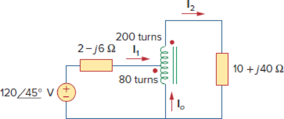
Chapter 13, Problem 68P
In the ideal autotransformer of Fig. 13.131, calculate Il, I2, and Io. Find the average power delivered to the load.
Expert Solution & Answer
Want to see the full answer?
Check out a sample textbook solution
Students have asked these similar questions
Q1/Sketch the root locus for the system shown in Figure 1 and find the following:
a. The exact point and gain where the locus crosses the jo-axis b. The breakaway point
on the real axis c. The range of K within which the system is stable d. Angles of
departure and arrival
R(s) +
K(s²-4s +20)
C(s)
(s+2)(s + 4)
Exam2
Subject: (Numerical Analysis)
Class: Third
Date: 27/4/2025
Time: 60 minutes
Q1. For what values of k does this system of equations has no solution? (use Gauss-Jordan eliminations)
kx + y + z = 1
x+ky + z = 1
x+y+kz=1
Consider the Difference equation of a causal Linear time-invariant (LTI) system given
by: (y(n) - 1.5y(n - 1) + 0.5y(n = 2) = x(n)
a) Implement the difference equation model of this system.
b) Find the system transfer function H(z).
c) For an input x(n) = 8(n), determine the output response y(n).
d) Verify the initial value theorem y(0) with part (c).
Chapter 13 Solutions
Fundamentals of Electric Circuits
Ch. 13.2 - Determine the voltage Vo in the circuit of Fig....Ch. 13.2 - Determine the phasor currents I1 and I2 in the...Ch. 13.3 - Prob. 3PPCh. 13.4 - Find the input impedance of the circuit in Fig....Ch. 13.4 - For the linear transformer in Fig. 13.26(a), find...Ch. 13.4 - Solve the problem in Example 13.1 (see Fig. 13.9)...Ch. 13.5 - The primary current to an ideal transformer rated...Ch. 13.5 - In the ideal transformer circuit of Fig. 13.38,...Ch. 13.5 - Find Vo in the circuit of Fig. 13.40. Figure 13.40...Ch. 13.6 - Refer to Fig. 13.43. If the two-winding...
Ch. 13.6 - In the autotransformer circuit of Fig. 13.45, find...Ch. 13.7 - Prob. 12PPCh. 13.8 - Prob. 13PPCh. 13.9 - Refer to Fig. 13.61. Calculate the turns ratio...Ch. 13.9 - Calculate the turns ratio of an ideal transformer...Ch. 13.9 - In Example 13.17, if the eight 100-W bulbs are...Ch. 13 - Refer to the two magnetically coupled coils of...Ch. 13 - Prob. 2RQCh. 13 - Prob. 3RQCh. 13 - Prob. 4RQCh. 13 - The ideal transformer in Fig. 13.70(a) has N2/N1 =...Ch. 13 - Prob. 6RQCh. 13 - A three-winding transformer is connected as...Ch. 13 - Prob. 8RQCh. 13 - Prob. 9RQCh. 13 - Prob. 10RQCh. 13 - For the three coupled coils in Fig. 13.72,...Ch. 13 - Using Fig. 13.73, design a problem to help other...Ch. 13 - Two coils connected in series-aiding fashion have...Ch. 13 - (a) For the coupled coils in Fig. 13.74(a), show...Ch. 13 - Two coils are mutually coupled, with L1 = 50 mH,...Ch. 13 - Given the circuit shown in Fig. 13.75, determine...Ch. 13 - For the circuit in Fig. 13.76, find Vo. Figure...Ch. 13 - Find v(t) for the circuit in Fig. 13.77.Ch. 13 - Prob. 9PCh. 13 - Find vo in the circuit of Fig. 13.79. Figure 13.79...Ch. 13 - Use mesh analysis to find ix in Fig. 13.80, where...Ch. 13 - Determine the equivalent Leq in the circuit of...Ch. 13 - For the circuit in Fig. 13.82, determine the...Ch. 13 - Obtain the Thevenin equivalent circuit for the...Ch. 13 - Find the Norton equivalent for the circuit in Fig....Ch. 13 - Obtain the Norton equivalent at terminals a-b of...Ch. 13 - In the circuit of Fig. 13.86, ZL is a 15-mH...Ch. 13 - Find the Thevenin equivalent to the left of the...Ch. 13 - Determine an equivalent T-section that can be used...Ch. 13 - Determine currents I1, I2, and I3 in the circuit...Ch. 13 - Prob. 21PCh. 13 - Find current Io in the circuit of Fig. 13.91.Ch. 13 - Let is = 5 cos (100t) A. Calculate the voltage...Ch. 13 - In the circuit of Fig. 13.93, (a) find the...Ch. 13 - Prob. 25PCh. 13 - Find Io in the circuit of Fig. 13.95. Switch the...Ch. 13 - Find the average power delivered to the 50-...Ch. 13 - In the circuit of Fig. 13.97, find the value of X...Ch. 13 - Prob. 29PCh. 13 - (a) Find the input impedance of the circuit in...Ch. 13 - Using Fig. 13.100, design a problem to help other...Ch. 13 - Two linear transformers are cascaded as shown in...Ch. 13 - Determine the input impedance of the air-core...Ch. 13 - Using Fig. 13.103, design a problem to help other...Ch. 13 - Find currents I1, I2, and I3 in the circuit of...Ch. 13 - As done in Fig. 13.33, obtain the relationships...Ch. 13 - A 2402,400-V rms step-up ideal transformer...Ch. 13 - Design a problem to help other students better...Ch. 13 - A 1,200240-V rms transformer has impedance on the...Ch. 13 - The primary of an ideal transformer with a turns...Ch. 13 - Given I2 = 2 A, determine the value of Is in Fig....Ch. 13 - For the circuit in Fig. 13.107, determine the...Ch. 13 - Obtain V1 and V2 in the ideal transformer circuit...Ch. 13 - In the ideal transformer circuit of Fig. 13.109,...Ch. 13 - For the circuit in Fig. 13.110, find the value of...Ch. 13 - (a) Find I1 and I2 in the circuit of Fig. 13.111...Ch. 13 - Prob. 47PCh. 13 - Using Fig. 13.113, design a problem to help other...Ch. 13 - Find current ix in the ideal transformer circuit...Ch. 13 - Prob. 50PCh. 13 - Use the concept of reflected impedance to find the...Ch. 13 - For the circuit in Fig. 13.117, determine the...Ch. 13 - Refer to the network in Fig. 13.118. (a) Find n...Ch. 13 - A transformer is used to match an amplifier with...Ch. 13 - For the circuit in Fig. 13.120, calculate the...Ch. 13 - Find the power absorbed by the 100- resistor in...Ch. 13 - For the ideal transformer circuit of Fig. 13.122...Ch. 13 - Determine the average power absorbed by each...Ch. 13 - In the circuit of Fig. 13.124, let vs = 165...Ch. 13 - Refer to the circuit in Fig. 13.125 on the...Ch. 13 - For the circuit in Fig. 13.126, find Il, I2, and...Ch. 13 - For the network in Fig. 13.127, find: (a) the...Ch. 13 - Find the mesh currents in th circuit of Fig....Ch. 13 - For the circuit in Fig. 13.129. find the turns...Ch. 13 - Calculate the average power dissipated by the 20-...Ch. 13 - Design a problem to help other students better...Ch. 13 - An autotransformer with a 40 percent tap is...Ch. 13 - In the ideal autotransformer of Fig. 13.131,...Ch. 13 - In the circuit of Fig. 13.131, N1 = 190 turns and...Ch. 13 - In the ideal transformer circuit shown in Fig....Ch. 13 - When individuals travel, their electrical...Ch. 13 - In order to meet an emergency, three single-phase...Ch. 13 - Figure 13.135 on the next page shows a three-phase...Ch. 13 - Consider the three-phase transformer shown in Fig....Ch. 13 - A balanced three-phase transformer bank with the...Ch. 13 - Using Fig. 13.138, design a problem to help other...Ch. 13 - The three-phase system of a town distributes power...Ch. 13 - Use PSpice or MultiSim to determine the mesh...Ch. 13 - Use PSpice or MultiSim to find I1, I2, and I3 in...Ch. 13 - Prob. 80PCh. 13 - Use PSpice or MultiSim to find I1, I2, and I3 in...Ch. 13 - A stereo amplifier circuit with ail output...Ch. 13 - A transformer having 2,400 turns on the primary...Ch. 13 - A radio receiver has an input resistance of 300 ....Ch. 13 - A step-down power transformer with a turns ratio...Ch. 13 - A 240120-V rms power transformer is rated at 10...Ch. 13 - A 4-kVA, 2,400240-V rms transformer has 250 turns...Ch. 13 - A 25,000240-V rms distribution transformer has a...Ch. 13 - A 4,800-V rms transmission line feeds a...Ch. 13 - A four-winding transformer (Fig. 13.146) is often...Ch. 13 - A 440/110-V ideal transformer can be connected to...Ch. 13 - Ten bulbs in parallel are supplied by a 7,200120-V...
Additional Engineering Textbook Solutions
Find more solutions based on key concepts
Assume a telephone signal travels through a cable at two-thirds the speed of light. How long does it take the s...
Electric Circuits. (11th Edition)
1.2 Explain the difference between geodetic and plane
surveys,
Elementary Surveying: An Introduction To Geomatics (15th Edition)
What is an uninitialized variable?
Starting Out with Programming Logic and Design (5th Edition) (What's New in Computer Science)
How does a computers main memory differ from its auxiliary memory?
Java: An Introduction to Problem Solving and Programming (8th Edition)
Using your text editor, enter (that is, type in) the C++ program shown in Display 1.8. Be certain to type the f...
Problem Solving with C++ (10th Edition)
CONCEPT QUESTIONS
15.CQ3 The ball rolls without slipping on the fixed surface as shown. What is the direction ...
Vector Mechanics for Engineers: Statics and Dynamics
Knowledge Booster


Learn more about
Need a deep-dive on the concept behind this application? Look no further. Learn more about this topic, electrical-engineering and related others by exploring similar questions and additional content below.Similar questions
- Q5B. Find the type of the controller in the following figures and use real values to find the transfer function of three of them[ Hint Pi,Pd and Lead,lag are found so put the controller with its corresponding compensator]. R₁ R₂ Rz HE C2 RA HE R₁ R2 RA とarrow_forwardQ1// Sketch the root locus for the unity feedback system. Where G(s)=)= K S3+252 +25 and find the following a. Sketch the asymptotes b. The exact point and gain where the locus crosses the jo-axis c. The breakaway point on the real axis d. The range of K within which the system is stable e. Angles of departure and arrival.arrow_forwardDetermine X(w) for the given function shown in Figure (1) by applying the differentiation property of the Fourier Transform. Figure (1) -1 x(t)arrow_forward
- Can you solve a question with a drawing Determine X(w) for the given function shown in Figure (1) by applying the differentiation property of the Fourier Transform. Figure (1) -1 x(t)arrow_forwardAn inductor has a current flow of 3 A when connected to a 240 V, 60 Hz power line. The inductor has a wire resistance of 15 Find the Q of the inductorarrow_forwardصورة من s94850121arrow_forward
- The joint density function of two continuous random variables X and Yis: p(x, y) = {Keós (x + y) Find (i) the constant K 0 2 0arrow_forwardShow all the steps please, Solve for the current through R2 if E2 is replaced by a current source of 10mA using superposition theorem. R5=470Ω R2=1000Ω R6=820Ωarrow_forwardPlease solve it by explaining the steps. I am trying to prepare for my exam tomorrow, so any tips and tricks to solve similar problems are highly appreciated. Plus, this is a past exam I am using to prepare.arrow_forwardPlease solve it by explaining the steps. I am trying to prepare for my exam today, so any tips and tricks to solve similar problems are highly appreciated. Plus, this is a past exam I am using to prepare.arrow_forwardIf C is the circle |z|=4 evaluate f f (z)dz for each of the following functions using residue. 1 f(z) = z(z²+6z+4)arrow_forwardIf C is the circle |z|=4 evaluate ff(z)dz for each of the following functions using residue. f(z) z(z²+6z+4)arrow_forwardarrow_back_iosSEE MORE QUESTIONSarrow_forward_ios
Recommended textbooks for you
 Introductory Circuit Analysis (13th Edition)Electrical EngineeringISBN:9780133923605Author:Robert L. BoylestadPublisher:PEARSON
 Delmar's Standard Textbook Of ElectricityElectrical EngineeringISBN:9781337900348Author:Stephen L. HermanPublisher:Cengage Learning
 Programmable Logic ControllersElectrical EngineeringISBN:9780073373843Author:Frank D. PetruzellaPublisher:McGraw-Hill Education
 Fundamentals of Electric CircuitsElectrical EngineeringISBN:9780078028229Author:Charles K Alexander, Matthew SadikuPublisher:McGraw-Hill Education
 Electric Circuits. (11th Edition)Electrical EngineeringISBN:9780134746968Author:James W. Nilsson, Susan RiedelPublisher:PEARSON
 Engineering ElectromagneticsElectrical EngineeringISBN:9780078028151Author:Hayt, William H. (william Hart), Jr, BUCK, John A.Publisher:Mcgraw-hill Education,
Introductory Circuit Analysis (13th Edition)
Electrical Engineering
ISBN:9780133923605
Author:Robert L. Boylestad
Publisher:PEARSON
Delmar's Standard Textbook Of Electricity
Electrical Engineering
ISBN:9781337900348
Author:Stephen L. Herman
Publisher:Cengage Learning
Programmable Logic Controllers
Electrical Engineering
ISBN:9780073373843
Author:Frank D. Petruzella
Publisher:McGraw-Hill Education
Fundamentals of Electric Circuits
Electrical Engineering
ISBN:9780078028229
Author:Charles K Alexander, Matthew Sadiku
Publisher:McGraw-Hill Education
Electric Circuits. (11th Edition)
Electrical Engineering
ISBN:9780134746968
Author:James W. Nilsson, Susan Riedel
Publisher:PEARSON
Engineering Electromagnetics
Electrical Engineering
ISBN:9780078028151
Author:Hayt, William H. (william Hart), Jr, BUCK, John A.
Publisher:Mcgraw-hill Education,
Series compensation of long transmission lines; Author: Georg Schett;https://www.youtube.com/watch?v=smOqSxFBvVU;License: Standard Youtube License