
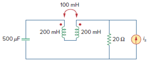
In the circuit of Fig. 13.93,
- (a) find the coupling coefficient,
- (b) calculate vo,
- (c) determine the energy stored in the coupled inductors at t = 2 s.
(a)
Calculate the coupling coefficient of the circuit in Figure 13.93.
Answer to Problem 24P
The coupling coefficient is
Explanation of Solution
Given data:
Refer to Figure 13.93 in the textbook for the circuit with coupled coils.
The value of
Calculation:
Consider the expression for the coefficient of coupling in the coupled coils.
Substitute 1 H for M, 4 H for
Conclusion:
Thus, the coupling coefficient is
(b)
Calculate the voltage
Answer to Problem 24P
The value of voltage
Explanation of Solution
Given data:
From Figure 13.93, the value of
Calculation:
Write the expression for the inductive reactance.
Write the expression for the capacitive reactance.
Substitute 4 H for
Substitute 2 H for
Substitute 1 H for
Substitute
Calculate load impedance
Modify the Figure 13.93 by transforming the time-domain circuit with coupled-coils to frequency domain of the circuit with coupled-coils. The frequency domain equivalent circuit is shown in Figure 1.
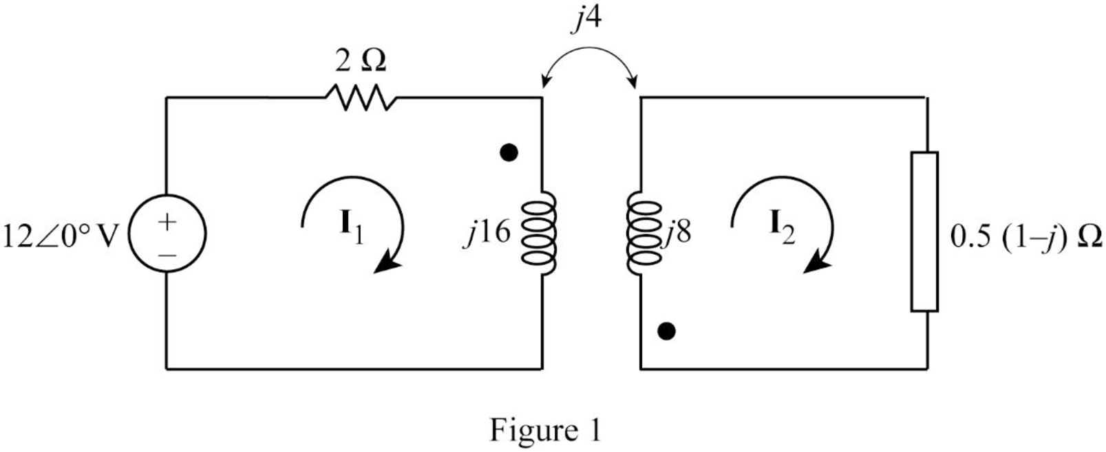
From Figure 1, consider that the loops 1 and 2 contain the currents
Apply Kirchhoff's voltage law to the loop 1 in Figure 1.
Apply Kirchhoff's voltage law to the loop 2 in Figure 1.
Write equations (3) and (4) in matrix form as follows.
Write the MATLAB code to solve the equation (5).
A = [(1+j*8) j*2;j*4 (0.5+j*7.5)];
B = [6; 0];
I = inv(A)*B
The output in command window:
I =
0.13036 - 0.84468i
-0.09912 + 0.44389i
From the MATLAB output, the currents
And
Write the expression for the voltage
Substitute
Convert the phasor form to time domain form.
Conclusion:
Thus, the value of voltage
(c)
Calculate the stored energy in the coupled coils at
Answer to Problem 24P
The energy stored in the coupled coils is
Explanation of Solution
Calculation:
From part (b), write the currents
Substitute 2 s for t in Equation (6).
Substitute 2 s for t in Equation (7).
Write the expression for the total energy stored in the coupled coils.
Substitute 4 H for
Conclusion:
Thus, the energy stored in the coupled coils is
Want to see more full solutions like this?
Chapter 13 Solutions
Fundamentals of Electric Circuits
Additional Engineering Textbook Solutions
Thinking Like an Engineer: An Active Learning Approach (4th Edition)
Starting Out With Visual Basic (8th Edition)
Mechanics of Materials (10th Edition)
Starting Out with Programming Logic and Design (5th Edition) (What's New in Computer Science)
Thermodynamics: An Engineering Approach
Elementary Surveying: An Introduction To Geomatics (15th Edition)

- consider the circuit below. Assume it uses ideal diodes with the details specified above. the left side of the circuit is basically a wheatstone bridge, hooked to the right side, which is a differential op amp. a) what is the voltage between junctions "A" and "B" if R2 is 201 ohms? b) what are the minimum and maximum values of R2 can be without the op amp hitting saturation?remember that for the diodes to be ideal you they have to have a turn on voltage of 0.6 volts.arrow_forwardThe capacitors in the circuit shown below have no energy stored in them and then switch “S1” closes at time t=0. Assume the ideal op amp does not saturate. As stated above assume the diodes are ideal with parameters specified above. Diodes are at 0.6 Volts Show the derivations of the mathematical equations for v(t) at Locations A and B for t≥ 0arrow_forwardPhase (deg) Magnitude (dB) -20 -40 -60 -80 -100 ° -90 -180 -270 10-1 (i) ° Problem 5 Consider a unity (negative) feedback system with a proportional controller. The Bode plot of the plant transfer function G(s) is given as below. System: sys Frequency (rad/s): 1 Magnitude (dB): 13.9 System: sys Frequency (rad/s): 14.9 Magnitude (dB): 6.58 System: sys Frequency (rad/s): 1 Phase (deg): -9.76 10° System: sys Frequency (rad/s): 25.6 Magnitude (dB): -0.0703 System: sys Frequency (rad/s): 41.3 Magnitude (dB): -8.06 System: sys Frequency (rad/s): 200 Magnitude (dB): -44.4 System: sys Frequency (rad/s): 14.9 Phase (deg): -110 System: sys Frequency (rad/s): 25.6 Phase (deg): -148 System: sys Frequency (rad/s): 41.3 Phase (deg): -180 System: sys Frequency (rad/s): 200 Phase (deg): -247 101 Frequency (rad/s) 102 Find the gain crossover frequency, phase crossover frequency, gain margin and phase margin of the system. Is the closed-loop system stable? (ii) What is the steady-state error of the…arrow_forward
- Problem 1 Consider the following system. In the figure, y(t) denotes the voltage across the capacitor. u(t) 1+ R W L + 0000 y(t) C Y(s) (i) Find the transfer function H(s): = of the system. U(s) Now suppose, R 10 KQ, L = 0.5 mH and C = 10 μF. (ii) Find the poles and zeros. Is the system BIBO stable? (iii) Compute settling time, rise time, peak time and % overshoot of the step response of the system. What the steady-state output for unit step input?arrow_forwardA 3-phase, 52 H.P, 50 Hz, 6-Pole, Y- connected induction motor runs at a speed of 980 rpm.The motor is supplied from 380 V mains and it takes a rated current of 80 A at 0.8 p.f. If the total stator losses are 1.7 kW, determine: the air-gap power, rotor copper loss, friction and windage losses?arrow_forwardelectric plants do hand writingarrow_forward
- please solve quickly. thank you!arrow_forwardPlease show all stepsarrow_forward12-3) PDF, mean, & variance A random variable has the PDF shown in the figure. a) Find the numerical value of the parameter K. b) Write the numerical expression for the PDF. c) Find the probability that the random variable is negative. d) Find the mean of x, the expected value of x², and the variance of x. K Px(x) 3 Xarrow_forward
 Delmar's Standard Textbook Of ElectricityElectrical EngineeringISBN:9781337900348Author:Stephen L. HermanPublisher:Cengage Learning