
Concept explainers
Videos
The hub diameter and projection for the gear of Prob. 13–51 are 100 and 37.5 mm, respectively. The face width of the gear is 50 mm. Locate bearings C and D on opposite sides, spacing C 10 mm from the gear on the hidden face (see figure) and D 10 mm from the hub face. Choose one as the thrust bearing, so that the axial load in the shaft is in compression. Find the output torque and the magnitudes and directions of the forces exerted by the bearings on the gearshaft.
The output torque.
The force exerted by the bearing
The force by the bearing
Answer to Problem 52P
The output torque is
The force exerted by the bearing
The force by the bearing
Explanation of Solution
The figure below shows the forces acting at the centre of the gear
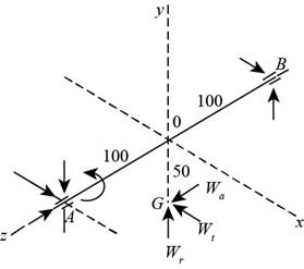
Figure-(1)
The tangential load on the centre of the gear is
The figure below shows the forces on the bearing
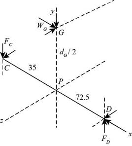
Figure-(2)
Write the expression for the linear velocity of the worm.
Here, the pitch diameter of the worm is
Write the expression for the tangential load on the gear.
Here, the power is
Write the expression for lead.
Here, the number of threads on worm is
Write the expression for the lead angle.
Write the expression for the force exerted by the by the gear on the worm.
Here, the normal pressure angle is
Write the expression for the sliding velocity.
Write the expression for the load in the y direction.
Write the expression for the load in the z direction.
Write the expression for vector form of the force against the worm.
The force on the gear will be equal but opposite to the force against the worm.
Write the expression for vector form of the force against the gear.
Write the diameter of the gear.
Here, the number of teeth on the gear is
The axial pitch and the transverse pitch is same hence
Write the position vector of
Here, the distance between the points
Write the position vector of
Here, the distance between the points
Write the moment equation at
Here, the force vector at
Write the expression for the force vector at
Here, the force in x-direction is
Write the force balance equation for the bearing
Conclusion:
Substitute
Substitute
Substitute
Substitute
Substitute
Convert the units of sliding velocity from
Refer to Figure 13-42 “Representative values of the coefficient of friction for worm gearing.” to obtain the friction coefficient as 0.043 with respect to sliding velocity as
Substitute
Substitute
Substitute
Substitute
Substitute
Substitute
Substitute
Substitute
Substitute
Solve Equation (XVII) for
Thus, the output torque is
Solve Equation (XVII) for
Solve Equation (XVII) for
Substitute
Thus, the force exerted by the bearing
Substitute
Thus, the force by the bearing
Want to see more full solutions like this?
Chapter 13 Solutions
Shigley's Mechanical Engineering Design (McGraw-Hill Series in Mechanical Engineering)


- Procedure:1- Cartesian system, 2D3D,type of support2- Free body diagram3 - Find the support reactions4- If you find a negativenumber then flip the force5- Find the internal force3D∑Fx=0∑Fy=0∑Fz=0∑Mx=0∑My=0\Sigma Mz=02D\Sigma Fx=0\Sigma Fy=0\Sigma Mz=05- Use method of sectionand cut the elementwhere you want to findthe internal force andkeep either side of thearrow_forwardProcedure: 1- Cartesian system, 2(D)/(3)D, type of support 2- Free body diagram 3 - Find the support reactions 4- If you find a negative number then flip the force 5- Find the internal force 3D \sum Fx=0 \sum Fy=0 \sum Fz=0 \sum Mx=0 \sum My=0 \Sigma Mz=0 2D \Sigma Fx=0 \Sigma Fy=0 \Sigma Mz=0 5- Use method of section and cut the element where you want to find the internal force and keep either side of the sectionarrow_forwardProcedure: 1- Cartesian system, 2(D)/(3)D, type of support 2- Free body diagram 3 - Find the support reactions 4- If you find a negative number then flip the force 5- Find the internal force 3D \sum Fx=0 \sum Fy=0 \sum Fz=0 \sum Mx=0 \sum My=0 \Sigma Mz=0 2D \Sigma Fx=0 \Sigma Fy=0 \Sigma Mz=0 5- Use method of section and cut the element where you want to find the internal force and keep either side of the sectionarrow_forward
- For each system below with transfer function G(s), plot the pole(s) on the s-plane. and indicate whether the system is: (a) "stable" (i.e., a bounded input will always result in a bounded output), (b) "marginally stable," or (c) "unstable" Sketch a rough graph of the time response to a step input. 8 a) G(s) = 5-5 8 b) G(s) = c) G(s) = = s+5 3s + 8 s² - 2s +2 3s +8 d) G(s): = s²+2s+2 3s+8 e) G(s): = s² +9 f) G(s): 8 00 == Sarrow_forwardPlease answer the following question. Include all work and plase explain. Graphs are provided below. "Consider the Mg (Magnesium) - Ni (Nickel) phase diagram shown below. This phase diagram contains two eutectic reactions and two intermediate phases (Mg2Ni and MgNi2). At a temperature of 505oC, determine what the composition of an alloy would need to be to contain a mass fraction of 0.20 Mg and 0.80 Mg2Ni."arrow_forwardThe triangular plate, having a 90∘∘ angle at AA, supports the load PP = 370 lblb as shown in (Figure 1).arrow_forward
- Design a 4-bar linkage to carry the body in Figure 1 through the two positions P1 and P2 at the angles shown in the figure. Use analytical synthesis with the free choice values z = 1.075, q= 210°, ß2 = −27° for left side and s = 1.24, y= 74°, ½ = − 40° for right side. φ 1.236 P2 147.5° 210° 2.138 P1 Figure 1 Xarrow_forwardDesign a 4-bar linkage to carry the body in Figure 1 through the two positions P1 and P2 at the angles shown in the figure. Use analytical synthesis with the free choice values z = 1.075, q= 210°, B₂ = −27° for left side and s = 1.24, y= 74°, ½ = − 40° for right side. 1.236 P2 147.5° 210° P1 Figure 1 2.138 Xarrow_forwardcan you explain how in a coordinate frame transformation: v = {v_n}^T {n-hat} and then it was found that {n-hat} = [C]^T {b-hat} so v_n = {v_n}^T [C]^T {b-hat}, how does that equation go from that to this --> v_n = [C]^T v_barrow_forward
- 6) If (k = 0,7 cm) find Imax for figure below. 225mm 100mm ثلاثاء. 100mm 150mm 75mm Ans: Tmax=45:27 N/cm F-400 Narrow_forwardThe man has a weight W and stands halfway along the beam. The beam is not smooth, but the planes at A and B are smooth (and plane A is horizontal). Determine the magnitude of the tension in the cord in terms of W and θ.arrow_forwardDetermine the reactions at the two supports for this plate. Express the reactions in Cartesian vector form.arrow_forward
 Elements Of ElectromagneticsMechanical EngineeringISBN:9780190698614Author:Sadiku, Matthew N. O.Publisher:Oxford University Press
 Mechanics of Materials (10th Edition)Mechanical EngineeringISBN:9780134319650Author:Russell C. HibbelerPublisher:PEARSON
 Thermodynamics: An Engineering ApproachMechanical EngineeringISBN:9781259822674Author:Yunus A. Cengel Dr., Michael A. BolesPublisher:McGraw-Hill Education
 Control Systems EngineeringMechanical EngineeringISBN:9781118170519Author:Norman S. NisePublisher:WILEY
 Mechanics of Materials (MindTap Course List)Mechanical EngineeringISBN:9781337093347Author:Barry J. Goodno, James M. GerePublisher:Cengage Learning
 Engineering Mechanics: StaticsMechanical EngineeringISBN:9781118807330Author:James L. Meriam, L. G. Kraige, J. N. BoltonPublisher:WILEY