
Shigley's Mechanical Engineering Design (McGraw-Hill Series in Mechanical Engineering)
10th Edition
ISBN: 9780073398204
Author: Richard G Budynas, Keith J Nisbett
Publisher: McGraw-Hill Education
expand_more
expand_more
format_list_bulleted
Concept explainers
Videos
Textbook Question
Chapter 13, Problem 32P
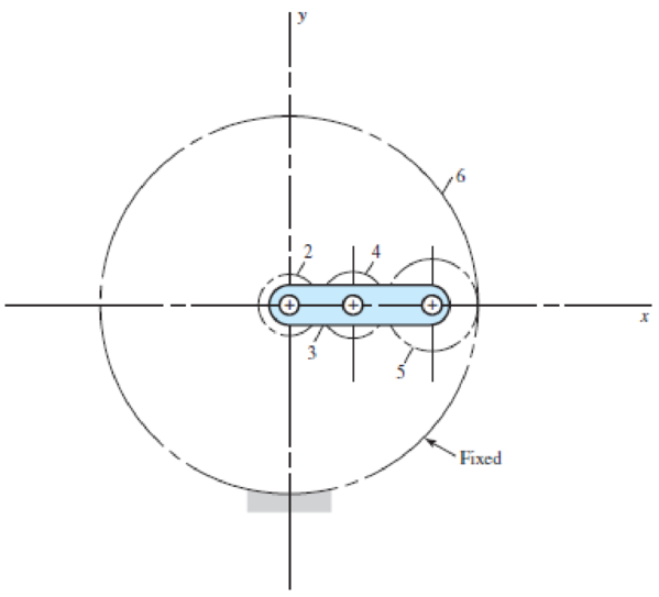
The 24T 6-pitch 20° pinion 2 shown in the figure rotates clockwise at 1000 rev/min and is driven at a power of 25 hp. Gears 4, 5, and 6 have 24, 36, and 144 teeth, respectively. What torque can arm 3 deliver to its output shaft? Draw free-body diagrams of the arm and of each gear and show all forces that act upon them.
Problem 13–32
Expert Solution & Answer

Trending nowThis is a popular solution!

Students have asked these similar questions
Student Name:
Student Id:
College of Applied Engineering
Al-Muzahmiyah Branch
Statics (AGE 1330) Section-1483
Quiz-2
Time: 20 minutes
Date: 16/02/2025
Q.1. A swinging door that weighs w=400.0N is supported by
hinges A and B so that the door can swing about a vertical'
axis passing through the hinges (as shown in below figure).
The door has a width of b=1.00m and the door slab has a
uniform mass density. The hinges are placed symmetrically
at the door's edge in such a way that the door's weight is
evenly distributed between them. The hinges are separated
by distance a=2.00m. Find the forces on the hinges when
the door rests half-open. Draw Free body diagram also.
[5 marks]
[CLO 1.2]
Mool
b
ర
a
2.0 m
B
1.0 m
For the walking-beam mechanism shown in Figure 3, find and plot the x and y coordinates of the
position of the coupler point P for one complete revolution of the crank O2A. Use the coordinate
system shown in Figure 3. Hint: Calculate them first with respect to the ground link 0204 and
then transform them into the global XY coordinate system.
y
-1.75
Ꮎ
Ꮎ
4
= 2.33
0242.22
L4
x
AP = 3.06
L2 = 1.0
W2
31°
B
03 L3 = 2.06
P
1
8
5
.06
6
7
P'
The link lengths, gear ratio (2), phase angle (Ø), and the value of 02 for some geared five bar
linkages are defined in Table 2. The linkage configuration and terminology are shown in Figure
2. For the rows assigned, find all possible solutions for angles 03 and 04 by the vector loop
method. Show your work in details: vector loop, vector equations, solution procedure.
Table 2
Row
Link 1 Link 2
Link 3
Link 4
Link 5
λ
Φ
Ө
a
6
1
7
9
4
2
30°
60°
P
y 4
YA
B
b
R4
R3
YA
A
Gear ratio:
a
02
d
05
r5
R5
R2
Phase angle: = 0₂-202
R1
05
02
r2
Figure 2.
04
X
Chapter 13 Solutions
Shigley's Mechanical Engineering Design (McGraw-Hill Series in Mechanical Engineering)
Ch. 13 - A 17-tooth spur pinion has a diametral pitch of 8...Ch. 13 - A 15-tooth spur pinion has a module of 3 mm and...Ch. 13 - A spur gearset has a module of 6 mm and a velocity...Ch. 13 - A 21-tooth spur pinion mates with a 28-tooth gear....Ch. 13 - A 20 straight-tooth bevel pinion having 14 teeth...Ch. 13 - A parallel helical gearset uses a 20-tooth pinion...Ch. 13 - A parallel helical gearset consists of a 19-tooth...Ch. 13 - To avoid the problem of interference in a pair of...Ch. 13 - Prob. 9PCh. 13 - Prob. 10P
Ch. 13 - Prob. 11PCh. 13 - Prob. 12PCh. 13 - Prob. 13PCh. 13 - Prob. 14PCh. 13 - A parallel-shaft gearset consists of an 18-tooth...Ch. 13 - The double-reduction helical gearset shown in the...Ch. 13 - Shaft a in the figure rotates at 600 rev/min in...Ch. 13 - The mechanism train shown consists of an...Ch. 13 - The figure shows a gear train consisting of a pair...Ch. 13 - A compound reverted gear trains are to be designed...Ch. 13 - Prob. 21PCh. 13 - Prob. 22PCh. 13 - Prob. 23PCh. 13 - A gearbox is to be designed with a compound...Ch. 13 - The tooth numbers for the automotive differential...Ch. 13 - Prob. 26PCh. 13 - In the reverted planetary train illustrated, find...Ch. 13 - Prob. 28PCh. 13 - Tooth numbers for the gear train shown in the...Ch. 13 - The tooth numbers for the gear train illustrated...Ch. 13 - Shaft a in the figure has a power input of 75 kW...Ch. 13 - The 24T 6-pitch 20 pinion 2 shown in the figure...Ch. 13 - The gears shown in the figure have a module of 12...Ch. 13 - The figure shows a pair of shaft-mounted spur...Ch. 13 - Prob. 35PCh. 13 - Prob. 36PCh. 13 - A speed-reducer gearbox containing a compound...Ch. 13 - For the countershaft in Prob. 3-72, p. 152, assume...Ch. 13 - Prob. 39PCh. 13 - Prob. 40PCh. 13 - Prob. 41PCh. 13 - Prob. 42PCh. 13 - The figure shows a 16T 20 straight bevel pinion...Ch. 13 - The figure shows a 10 diametral pitch 18-tooth 20...Ch. 13 - Prob. 45PCh. 13 - The gears shown in the figure have a normal...Ch. 13 - Prob. 47PCh. 13 - Prob. 48PCh. 13 - Prob. 49PCh. 13 - The figure shows a double-reduction helical...Ch. 13 - A right-hand single-tooth hardened-steel (hardness...Ch. 13 - The hub diameter and projection for the gear of...Ch. 13 - A 2-tooth left-hand worm transmits 34 hp at 600...
Knowledge Booster


Learn more about
Need a deep-dive on the concept behind this application? Look no further. Learn more about this topic, mechanical-engineering and related others by exploring similar questions and additional content below.Similar questions
- Problem 4 A .025 lb bullet C is fired at end B of the 15-lb slender bar AB. The bar is initially at rest, and the initial velocity of the bullet is 1500 ft/s as shown. Assuming that the bullet becomes embedded in the bar, find (a) the angular velocity @2 of the bar immediately after impact, and (b) the percentage loss of kinetic energy as a result of the impact. (c) After the impact, does the bar swing up 90° and reach the horizontal? If it does, what is its angular velocity at this point? Answers: (a). @2=1.6 rad/s; (b). 99.6% loss = (c). Ah2 0.212 ft. The bar does not reach horizontal. y X 4 ft 15 lb V₁ 1500 ft/s 0.025 lb C 30°7 B Aarrow_forwardsubject: combustion please include complete solution, no rounding off, with diagram/explanation etc. In a joule cycle, intake of the compressor is 40,000 cfm at 0.3 psig and 90 deg F. The compression ratio is 6.0 and the inlet temperature at the turbine portion is 1900R while at the exit, it is 15 psi. Calculate for the back work ratio in percent.arrow_forwardsubject: combustion please include complete solution, no rounding off, with diagram/explanation etc. A gasoline engine, utilizing cold air, recorded a work of 431 BTU/lb at a maximum temperature of 3,273 K and 1112 deg F temperature at the beginning of constant volume heat addition. What is the compression ratio?arrow_forward
- subject: combustion please do step by step solution and no rounding off, complete solution with diagram/explanation if needed etc. thank you! Air enters the compressor at 101,320 Pascals, 305.15K, and leaves at a pressure of 0.808MPa. The air is heated to 990.15K in the combustion chamber. For a net output of 2,125,000 Watts, find the rate of flow of air per second.arrow_forwardThe link lengths and the value of 2 and offset for some fourbar crank-slide linkages are defined in Table 1. The linkage configuration and terminology are shown in Figure 1. For the rows assigned, find (a) all possible solutions for angle & and slider position d by vector loop method. (b) the transmission angle corresponding to angle 03. (Hint: Treat the vector R4 as virtual rocker) Show your work in details: vector loop, vector equations, solution procedure. Table 1 Row Link 2 Link 3 Offset Ө a 1.4 4 1 45° b 3 8 2 -30° C 5 20 -5 225° 03 slider axis B X offset Link 2 A R3 Link 3 R4 04 R2 02 R1 d Figure 1. Xarrow_forward4. Two links made of heat treated 6061 aluminum (Sy = 276 MPa, Sys = 160 MPa) are pinned together using a steel dowel pin (Sy = 1398 MPa, Sys = 806 MPa) as shown below. The links are to support a load P with a factor of safety of at least 2.0. Determine if the link will fail first by tearout, direct shear of the pin, bearing stress on the link, or tensile stress at section AA. (Hint: find the load P for each case and choose the case that gives the smallest load.) P 8 mm P 8 mm ¡+A 3 mm →A 10 mm Parrow_forward
- 1. For a feature other than a sphere, circularity is where: A. The axis is a straight line B. The modifier is specified with a size dimension C. All points of the surface intersected by any plane perpendicular to an axis or spine (curved line) are equidistant from that axis or spine D. All points of the surface intersected by any plane passing through a common center are equidistant from that center 2. What type of variation is limited by a circularity toler- ance zone? A. Ovality B. Tapering C. Bending D. Warping 3. How does the Rule #1 boundary affect the application of a circularity tolerance? A. The modifier must be used. B. The feature control frame must be placed next to the size dimension. C. The circularity tolerance value must be less than the limits of size tolerance. D. Circularity cannot be applied where a Rule #1 boundary exists. 4. A circularity tolerance may use a modifier. A. Ø B. F C. M D. ℗ 5. A real-world application for a circularity tolerance is: A. Assembly (i.e.,…arrow_forward3. A steel bar is pinned to a vertical support column by a 10 mm diameter hardened dowel pin, Figure 1. For P = 7500 N, find: a. the shear stress in the pin, b. the direct bearing stress on the hole in the bar, c. the minimum value of d to prevent tearout failure if the steel bar has a shear strength of 175 MPa. support column pin bar thickness of bar = 8 mm h d 150 mmarrow_forwardA press that delivers 115 strokes per minute, each stroke providing a force of 7826 N throughout a distance of 18 mm. The press efficiency is 90% and is driven by a 1749-rpm motor. Determine average torque that must be provided by the motor in the units of N-m.arrow_forward
arrow_back_ios
SEE MORE QUESTIONS
arrow_forward_ios
Recommended textbooks for you
 Elements Of ElectromagneticsMechanical EngineeringISBN:9780190698614Author:Sadiku, Matthew N. O.Publisher:Oxford University Press
 Mechanics of Materials (10th Edition)Mechanical EngineeringISBN:9780134319650Author:Russell C. HibbelerPublisher:PEARSON
 Thermodynamics: An Engineering ApproachMechanical EngineeringISBN:9781259822674Author:Yunus A. Cengel Dr., Michael A. BolesPublisher:McGraw-Hill Education
 Control Systems EngineeringMechanical EngineeringISBN:9781118170519Author:Norman S. NisePublisher:WILEY
 Mechanics of Materials (MindTap Course List)Mechanical EngineeringISBN:9781337093347Author:Barry J. Goodno, James M. GerePublisher:Cengage Learning
 Engineering Mechanics: StaticsMechanical EngineeringISBN:9781118807330Author:James L. Meriam, L. G. Kraige, J. N. BoltonPublisher:WILEY
Elements Of Electromagnetics
Mechanical Engineering
ISBN:9780190698614
Author:Sadiku, Matthew N. O.
Publisher:Oxford University Press
Mechanics of Materials (10th Edition)
Mechanical Engineering
ISBN:9780134319650
Author:Russell C. Hibbeler
Publisher:PEARSON
Thermodynamics: An Engineering Approach
Mechanical Engineering
ISBN:9781259822674
Author:Yunus A. Cengel Dr., Michael A. Boles
Publisher:McGraw-Hill Education
Control Systems Engineering
Mechanical Engineering
ISBN:9781118170519
Author:Norman S. Nise
Publisher:WILEY
Mechanics of Materials (MindTap Course List)
Mechanical Engineering
ISBN:9781337093347
Author:Barry J. Goodno, James M. Gere
Publisher:Cengage Learning
Engineering Mechanics: Statics
Mechanical Engineering
ISBN:9781118807330
Author:James L. Meriam, L. G. Kraige, J. N. Bolton
Publisher:WILEY
Power Transmission; Author: Terry Brown Mechanical Engineering;https://www.youtube.com/watch?v=YVm4LNVp1vA;License: Standard Youtube License