
Concept explainers
Videos
(a)
Find the acceleration of block A for each system.
(a)
Answer to Problem 12.15P
The acceleration of block A for system 1 is
The acceleration of block A for system 2 is
The acceleration of block A for system 1 is
Explanation of Solution
Calculation:
Sketch the general diagram of systems as shown in Figure (1).
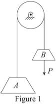
Write total length of cable connecting block A and block B.
Here,
Differentiate Equation (1) with respect to t to write velocity of the blocks.
Here,
Differentiate Equation (2) with respect to t to write acceleration of the blocks.
First of all check the required static friction with static friction to maintain equilibrium.
Sketch the free body diagram and kinetic diagram of block A as shown in Figure (2).
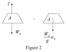
Refer Figure (2).
Consider downward direction as positive.
Apply Newton’s law of motion along y-axis.
Here, T is the tension in the cable,
Sketch the free body diagram and kinetic diagram of block B as shown in Figure (3).
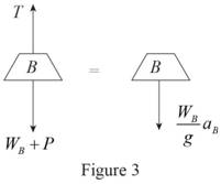
Refer Figure (3).
Consider downward direction as positive.
Apply Newton’s law of motion along y-axis.
Find the equation of acceleration of block A.
Here, T is the tension in the cable,
Substitute
The initial velocity of block A is zero.
Find the equation of velocity of block A using kinematics:
Here,
Substitute At
Find the equation of time required for block A to reach any velocity.
Find the acceleration of block A
Substitute 200 lb for
Therefore, the acceleration of block A for system 1 is
Find the acceleration of block A
Substitute 200 lb for
Therefore, the acceleration of block A for system 2 is
Find the acceleration of block A
Substitute 2200 lb for
Therefore, the acceleration of block A for system 2 is
(b)
Find the velocity of block A for each system after it has moved through 10 ft
(b)
Answer to Problem 12.15P
The velocity of block A for system 1 after it has moved through 10 ft is
The velocity of block A for system 2 after it has moved through 10 ft is
The velocity of block A for system 3 after it has moved through 10 ft is
Explanation of Solution
Calculation:
Find the velocity of block A for system 1
Substitute
Thus, the velocity of block A for system 1 after it has moved through 10 ft is
Find the velocity of block A for system 2
Substitute
Thus, the velocity of block A for system 2 after it has moved through 10 ft is
Find the velocity of block A for system 3
Substitute
Thus, the velocity of block A for system 3 after it has moved through 10 ft is
(c)
Find the time required for block A to reach a velocity of 20 ft/s
(c)
Answer to Problem 12.15P
The time required for block A for system 1 to reach a velocity of 20 ft/s is
The time required for block A for system 2 to reach a velocity of 20 ft/s is
The time required for block A for system 3 to reach a velocity of 20 ft/s is
Explanation of Solution
Calculation:
Find the time required for block A for system 1
Substitute
Thus, the time of required for block A for system 1 to reach a velocity of 20 ft/s is
Find the time required for block A for system 2
Substitute
Thus, the time of required for block A for system 2 to reach a velocity of 20 ft/s is
Find the time required for block A for system 3
Substitute
Thus, the time of required for block A for system 3 to reach a velocity of 20 ft/s is
Want to see more full solutions like this?
Chapter 12 Solutions
VEC MECH 180-DAT EBOOK ACCESS(STAT+DYNA)


- reaction at a is 1.6 wL (pos) handwritten solutions only please. correct answers upvotedarrow_forward1 8 4 Add numbers so that the sum of any row or column equals .30 Use only these numbers: .1.2.3.4.5.6.10.11.12.12.13.14.14arrow_forwardUppgift 2 (9p) I77777 20 kN 10 kN/m 4 [m] 2 2 Bestäm tvärkrafts- och momentdiagram för balken i figuren ovan. Extrempunkter ska anges med både läge och värde i diagrammen.arrow_forward
- **Problem 8-45.** The man has a mass of 60 kg and the crate has a mass of 100 kg. If the coefficient of static friction between his shoes and the ground is \( \mu_s = 0.4 \) and between the crate and the ground is \( \mu_c = 0.3 \), determine if the man is able to move the crate using the rope-and-pulley system shown. **Diagram Explanation:** The diagram illustrates a scenario where a man is attempting to pull a crate using a rope-and-pulley system. The setup is as follows: - **Crate (C):** Positioned on the ground with a rope attached. - **Rope:** Connects the crate to a pulley system and extends to the man. - **Pulley on Tree:** The rope runs over a pulley mounted on a tree which redirects the rope. - **Angles:** - The rope between the crate and tree forms a \(30^\circ\) angle with the horizontal. - The rope between the tree and the man makes a \(45^\circ\) angle with the horizontal. - **Man (A):** Pulling on the rope with the intention of moving the crate. This arrangement tests the…arrow_forwardplease solve this problems follow what the question are asking to do please show me step by steparrow_forwardplease first write the line action find the forces and them solve the problem step by steparrow_forward
- please solve this problem what the problem are asking to solve please explain step by step and give me the correct answerarrow_forwardplease help me to solve this problem step by steparrow_forwardplease help me to solve this problem and determine the stress for each point i like to be explained step by step with the correct answerarrow_forward
 Elements Of ElectromagneticsMechanical EngineeringISBN:9780190698614Author:Sadiku, Matthew N. O.Publisher:Oxford University Press
 Mechanics of Materials (10th Edition)Mechanical EngineeringISBN:9780134319650Author:Russell C. HibbelerPublisher:PEARSON
 Thermodynamics: An Engineering ApproachMechanical EngineeringISBN:9781259822674Author:Yunus A. Cengel Dr., Michael A. BolesPublisher:McGraw-Hill Education
 Control Systems EngineeringMechanical EngineeringISBN:9781118170519Author:Norman S. NisePublisher:WILEY
 Mechanics of Materials (MindTap Course List)Mechanical EngineeringISBN:9781337093347Author:Barry J. Goodno, James M. GerePublisher:Cengage Learning
 Engineering Mechanics: StaticsMechanical EngineeringISBN:9781118807330Author:James L. Meriam, L. G. Kraige, J. N. BoltonPublisher:WILEY