
Concept explainers
Videos
(a)
Find the acceleration of block A for each system.
(a)
Answer to Problem 12.15P
The acceleration of block A for system 1 is
The acceleration of block A for system 2 is
The acceleration of block A for system 1 is
Explanation of Solution
Calculation:
Sketch the general diagram of systems as shown in Figure (1).
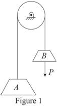
Write total length of cable connecting block A and block B.
Here,
Differentiate Equation (1) with respect to t to write velocity of the blocks.
Here,
Differentiate Equation (2) with respect to t to write acceleration of the blocks.
First of all check the required static friction with static friction to maintain equilibrium.
Sketch the free body diagram and kinetic diagram of block A as shown in Figure (2).
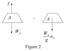
Refer Figure (2).
Consider downward direction as positive.
Apply Newton’s law of motion along y-axis.
Here, T is the tension in the cable,
Sketch the free body diagram and kinetic diagram of block B as shown in Figure (3).
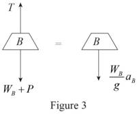
Refer Figure (3).
Consider downward direction as positive.
Apply Newton’s law of motion along y-axis.
Find the equation of acceleration of block A.
Here, T is the tension in the cable,
Substitute
The initial velocity of block A is zero.
Find the equation of velocity of block A using kinematics:
Here,
Substitute At
Find the equation of time required for block A to reach any velocity.
Find the acceleration of block A
Substitute 200 lb for
Therefore, the acceleration of block A for system 1 is
Find the acceleration of block A
Substitute 200 lb for
Therefore, the acceleration of block A for system 2 is
Find the acceleration of block A
Substitute 2200 lb for
Therefore, the acceleration of block A for system 2 is
(b)
Find the velocity of block A for each system after it has moved through 10 ft
(b)
Answer to Problem 12.15P
The velocity of block A for system 1 after it has moved through 10 ft is
The velocity of block A for system 2 after it has moved through 10 ft is
The velocity of block A for system 3 after it has moved through 10 ft is
Explanation of Solution
Calculation:
Find the velocity of block A for system 1
Substitute
Thus, the velocity of block A for system 1 after it has moved through 10 ft is
Find the velocity of block A for system 2
Substitute
Thus, the velocity of block A for system 2 after it has moved through 10 ft is
Find the velocity of block A for system 3
Substitute
Thus, the velocity of block A for system 3 after it has moved through 10 ft is
(c)
Find the time required for block A to reach a velocity of 20 ft/s
(c)
Answer to Problem 12.15P
The time required for block A for system 1 to reach a velocity of 20 ft/s is
The time required for block A for system 2 to reach a velocity of 20 ft/s is
The time required for block A for system 3 to reach a velocity of 20 ft/s is
Explanation of Solution
Calculation:
Find the time required for block A for system 1
Substitute
Thus, the time of required for block A for system 1 to reach a velocity of 20 ft/s is
Find the time required for block A for system 2
Substitute
Thus, the time of required for block A for system 2 to reach a velocity of 20 ft/s is
Find the time required for block A for system 3
Substitute
Thus, the time of required for block A for system 3 to reach a velocity of 20 ft/s is
Want to see more full solutions like this?
Chapter 12 Solutions
Vector Mechanics for Engineers: Statics and Dynamics


- Problem (14): A pump is being used to lift water from an underground tank through a pipe of diameter (d) at discharge (Q). The total head loss until the pump entrance can be calculated as (h₁ = K[V²/2g]), h where (V) is the flow velocity in the pipe. The elevation difference between the pump and tank surface is (h). Given the values of h [cm], d [cm], and K [-], calculate the maximum discharge Q [Lit/s] beyond which cavitation would take place at the pump entrance. Assume Turbulent flow conditions. Givens: h = 120.31 cm d = 14.455 cm K = 8.976 Q Answers: (1) 94.917 lit/s (2) 49.048 lit/s ( 3 ) 80.722 lit/s 68.588 lit/s 4arrow_forwardProblem (13): A pump is being used to lift water from the bottom tank to the top tank in a galvanized iron pipe at a discharge (Q). The length and diameter of the pipe section from the bottom tank to the pump are (L₁) and (d₁), respectively. The length and diameter of the pipe section from the pump to the top tank are (L2) and (d2), respectively. Given the values of Q [L/s], L₁ [m], d₁ [m], L₂ [m], d₂ [m], calculate total head loss due to friction (i.e., major loss) in the pipe (hmajor-loss) in [cm]. Givens: L₁,d₁ Pump L₂,d2 오 0.533 lit/s L1 = 6920.729 m d1 = 1.065 m L2 = 70.946 m d2 0.072 m Answers: (1) 3.069 cm (2) 3.914 cm ( 3 ) 2.519 cm ( 4 ) 1.855 cm TABLE 8.1 Equivalent Roughness for New Pipes Pipe Riveted steel Concrete Wood stave Cast iron Galvanized iron Equivalent Roughness, & Feet Millimeters 0.003-0.03 0.9-9.0 0.001-0.01 0.3-3.0 0.0006-0.003 0.18-0.9 0.00085 0.26 0.0005 0.15 0.045 0.000005 0.0015 0.0 (smooth) 0.0 (smooth) Commercial steel or wrought iron 0.00015 Drawn…arrow_forwardThe flow rate is 12.275 Liters/s and the diameter is 6.266 cm.arrow_forward
- An experimental setup is being built to study the flow in a large water main (i.e., a large pipe). The water main is expected to convey a discharge (Qp). The experimental tube will be built at a length scale of 1/20 of the actual water main. After building the experimental setup, the pressure drop per unit length in the model tube (APm/Lm) is measured. Problem (20): Given the value of APm/Lm [kPa/m], and assuming pressure coefficient similitude, calculate the drop in the pressure per unit length of the water main (APP/Lp) in [Pa/m]. Givens: AP M/L m = 590.637 kPa/m meen Answers: ( 1 ) 59.369 Pa/m ( 2 ) 73.83 Pa/m (3) 95.443 Pa/m ( 4 ) 44.444 Pa/m *******arrow_forwardFind the reaction force in y if Ain = 0.169 m^2, Aout = 0.143 m^2, p_in = 0.552 atm, Q = 0.367 m^3/s, α = 31.72 degrees. The pipe is flat on the ground so do not factor in weight of the pipe and fluid.arrow_forwardFind the reaction force in x if Ain = 0.301 m^2, Aout = 0.177 m^2, p_in = 1.338 atm, Q = 0.669 m^3/s, and α = 37.183 degreesarrow_forward
- Problem 5: Three-Force Equilibrium A structural connection at point O is in equilibrium under the action of three forces. • • . Member A applies a force of 9 kN vertically upward along the y-axis. Member B applies an unknown force F at the angle shown. Member C applies an unknown force T along its length at an angle shown. Determine the magnitudes of forces F and T required for equilibrium, assuming 0 = 90° y 9 kN Aarrow_forwardProblem 19: Determine the force in members HG, HE, and DE of the truss, and state if the members are in tension or compression. 4 ft K J I H G B C D E F -3 ft -3 ft 3 ft 3 ft 3 ft- 1500 lb 1500 lb 1500 lb 1500 lb 1500 lbarrow_forwardProblem 14: Determine the reactions at the pin A, and the tension in cord. Neglect the thickness of the beam. F1=26kN F2 13 12 80° -2m 3marrow_forward
- Problem 22: Determine the force in members GF, FC, and CD of the bridge truss and state if the members are in tension or compression. F 15 ft B D -40 ft 40 ft -40 ft 40 ft- 5 k 10 k 15 k 30 ft Earrow_forwardProblem 20: Determine the force in members BC, HC, and HG. After the truss is sectioned use a single equation of equilibrium for the calculation of each force. State if the members are in tension or compression. 5 kN 4 kN 4 kN 3 kN 2 kN B D E F 3 m -5 m- -5 m- 5 m 5 m-arrow_forwardAn experimental setup is being built to study the flow in a large water main (i.e., a large pipe). The water main is expected to convey a discharge (Qp). The experimental tube will be built at a length scale of 1/20 of the actual water main. After building the experimental setup, the pressure drop per unit length in the model tube (APm/Lm) is measured. Problem (19): Given the value of Qp [m³/s], and assuming Reynolds number similitude between the water main and experimental tube, calculate the flow rate in the model tube (Qm) in [lit/s]. = 30.015 m^3/sarrow_forward
 Elements Of ElectromagneticsMechanical EngineeringISBN:9780190698614Author:Sadiku, Matthew N. O.Publisher:Oxford University Press
 Mechanics of Materials (10th Edition)Mechanical EngineeringISBN:9780134319650Author:Russell C. HibbelerPublisher:PEARSON
 Thermodynamics: An Engineering ApproachMechanical EngineeringISBN:9781259822674Author:Yunus A. Cengel Dr., Michael A. BolesPublisher:McGraw-Hill Education
 Control Systems EngineeringMechanical EngineeringISBN:9781118170519Author:Norman S. NisePublisher:WILEY
 Mechanics of Materials (MindTap Course List)Mechanical EngineeringISBN:9781337093347Author:Barry J. Goodno, James M. GerePublisher:Cengage Learning
 Engineering Mechanics: StaticsMechanical EngineeringISBN:9781118807330Author:James L. Meriam, L. G. Kraige, J. N. BoltonPublisher:WILEY