
EE 98: Fundamentals of Electrical Circuits - With Connect Access
6th Edition
ISBN: 9781259981807
Author: Alexander
Publisher: MCG
expand_more
expand_more
format_list_bulleted
Concept explainers
Videos
Textbook Question
Chapter 12, Problem 15P
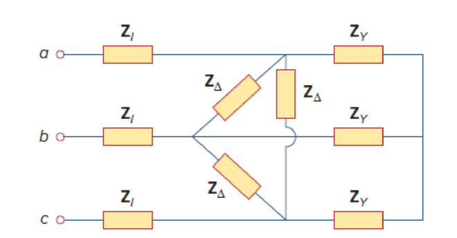
The circuit in Fig. 12.48 is excited by a balanced three-phase source with a line voltage of 210 V. If Zl = 1 + j1 Ω, ZΔ = 24 − j30 Ω, and ZY = 12 + j5 Ω, determine the magnitude of the line current of the combined loads.
Expert Solution & Answer
Want to see the full answer?
Check out a sample textbook solution
Students have asked these similar questions
I need help fixing this MATLAB code: as I try to get it working there were some problems:
I need help in construct a matlab code to find the voltage of VR1 to VR4, the currents, and the watts based on that circuit.
Q2: Using D flip-flops, design a synchronous counter. The counter counts in the sequence
1,3,5,7, 1,7,5,3,1,3,5,7,.... when its enable input x is equal to 1; otherwise, the counter
count 0.
Chapter 12 Solutions
EE 98: Fundamentals of Electrical Circuits - With Connect Access
Ch. 12.2 - Given that Vbn=22030V, find Van and Vcn, assuming...Ch. 12.3 - A Y-connected balanced three-phase generator with...Ch. 12.4 - One line voltage of a balanced Y-connected source...Ch. 12.5 - A positive-sequence, balanced -connected source...Ch. 12.6 - In a balanced -Y circuit, Vab=44015 and ZY = (12 +...Ch. 12.7 - For the Y-Y circuit in Practice Prob. 12.2,...Ch. 12.7 - Calculate the line current required for a 30-kW...Ch. 12.7 - Assume that the two balanced loads in Fig....Ch. 12.8 - The unbalanced -load of Fig. 12.24 is supplied by...Ch. 12.8 - Find the line currents in the unbalanced...
Ch. 12.9 - Prob. 11PPCh. 12.9 - For the unbalanced circuit in Fig. 12.32, use...Ch. 12.10 - Repeat Example 12.13 for the network in Fig. 12.24...Ch. 12.10 - Let the line voltage VL = 208 V and the wattmeter...Ch. 12.10 - If the load in Fig. 12.35 is delta-connected with...Ch. 12 - What is the phase sequence of a three-phase motor...Ch. 12 - If in an acb phase sequence, , then Vcn is:Ch. 12 - Which of these is not a required condition for a...Ch. 12 - Prob. 4RQCh. 12 - Prob. 5RQCh. 12 - In a Y-Y system, a line voltage of 220 V produces...Ch. 12 - In a - system, a phase voltage of 100 V produces a...Ch. 12 - When a Y-connected load is supplied by voltages in...Ch. 12 - Prob. 9RQCh. 12 - Prob. 10RQCh. 12 - If Vab = 400 V in a balanced Y-connected...Ch. 12 - What is the phase sequence of a balanced...Ch. 12 - Given a balanced Y-connected three-phase generator...Ch. 12 - A three-phase system with abc sequence and VL =...Ch. 12 - For a Y-connected load, the time-domain...Ch. 12 - Using Fig. 12.41, design a problem to help other...Ch. 12 - Obtain the line currents in the three-phase...Ch. 12 - In a balanced three-phase Y-Y system, the source...Ch. 12 - A balanced Y-Y four-wire system has phase voltages...Ch. 12 - For the circuit in Fig. 12.43, determine the...Ch. 12 - In the Y- system shown in Fig. 12.44, the source...Ch. 12 - Using Fig. 12.45, design a problem to help other...Ch. 12 - In the balanced three-phase Y- system in Fig....Ch. 12 - Obtain the line currents in the three-phase...Ch. 12 - The circuit in Fig. 12.48 is excited by a balanced...Ch. 12 - A balanced delta-connected load has a phase...Ch. 12 - A positive sequence wye-connected source where ,...Ch. 12 - If Van = 22060 V in the network of Fig. 12.49,...Ch. 12 - For the - circuit of Fig. 12.50, calculate the...Ch. 12 - Prob. 20PCh. 12 - Three 440-V generators form a delta-connected...Ch. 12 - Find the line currents IaA, IbB, and IcC in the...Ch. 12 - A balanced delta connected source is connected to...Ch. 12 - A balanced delta-connected source has phase...Ch. 12 - In the circuit of Fig. 12.54, if , , , find the...Ch. 12 - Using Fig. 12.55, design a problem to help other...Ch. 12 - A -connected source supplies power to a...Ch. 12 - The line-to-line voltages in a Y-load have a...Ch. 12 - A balanced three-phase Y- system has V rms and Z =...Ch. 12 - In Fig. 12.56, the rms value of the line voltage...Ch. 12 - A balanced delta-connected load is supplied by a...Ch. 12 - Design a problem to help other students better...Ch. 12 - A three-phase source delivers 4.8 kVA to a...Ch. 12 - A balanced wye-connected load with a phase...Ch. 12 - Three equal impedances, 60 + j30 each, are...Ch. 12 - A 4200-V, three-phase transmission line has an...Ch. 12 - The total power measured in a three-phase system...Ch. 12 - Given the circuit in Fig. 12.57 below, find the...Ch. 12 - Find the real power absorbed by the load in Fig....Ch. 12 - For the three-phase circuit in Fig. 12.59, find...Ch. 12 - A balanced delta-connected load draws 5 kW at a...Ch. 12 - A balanced three-phase generator delivers 7.2 kW...Ch. 12 - Refer to Fig. 12.48. Obtain the complex power...Ch. 12 - A three-phase line has an impedance of 1 + j3 per...Ch. 12 - A balanced wye-connected load is connected to the...Ch. 12 - A three-phase load consists of three 100-...Ch. 12 - The following three parallel-connected three-phase...Ch. 12 - A balanced, positive-sequence wye-connected source...Ch. 12 - Each phase load consists of a 20- resistor and a...Ch. 12 - A balanced three-phase source with VL = 240 V rms...Ch. 12 - Consider the wye-delta system shown in Fig. 12.60....Ch. 12 - A four-wire wye-wye circuit has...Ch. 12 - Using Fig. 12.61, design a problem that will help...Ch. 12 - A balanced three-phase Y-source with VP = 880 V...Ch. 12 - A three-phase supply, with the line-to-line...Ch. 12 - Using Fig. 12.63, design a problem to help other...Ch. 12 - Determine the line currents for the three-phase...Ch. 12 - Solve Prob. 12.10 using PSpice or MultiSim. For...Ch. 12 - The source in Fig. 12.65 is balanced and exhibits...Ch. 12 - Use PSpice or MultiSim to determine Io in the...Ch. 12 - Given the circuit in Fig. 12.67, use PSpice or...Ch. 12 - Using Fig. 12.68, design a problem to help other...Ch. 12 - Use PSpice or MultiSim to find currents IaA and...Ch. 12 - For the circuit in Fig. 12.58, use PSpice or...Ch. 12 - A balanced three-phase circuit is shown in Fig....Ch. 12 - A three-phase, four-wire system operating with a...Ch. 12 - As shown in Fig. 12.72, a three-phase four-wire...Ch. 12 - Meter readings for a three-phase wye-connected...Ch. 12 - A certain store contains three balanced...Ch. 12 - The two-wattmeter method gives P1=1200W and...Ch. 12 - In Fig. 12.73, two wattmeters are properly...Ch. 12 - If wattmeters W1 and W2 are properly connected...Ch. 12 - For the circuit displayed in Fig. 12.74, find the...Ch. 12 - Predict the wattmeter readings for the circuit in...Ch. 12 - Prob. 75PCh. 12 - Show that the I2R losses will be higher for a...Ch. 12 - A three-phase generator supplied 10 kVA at a power...Ch. 12 - Prob. 78CPCh. 12 - A balanced three-phase generator has an abc phase...Ch. 12 - A balanced three-phase source furnishes power to...Ch. 12 - A professional center is supplied by a balanced...Ch. 12 - A balanced three-phase system has a distribution...Ch. 12 - A commercially available three-phase inductive...Ch. 12 - Figure 12.76 displays a three-phase...Ch. 12 - Design a three-phase heater with suitable...Ch. 12 - For the single-phase three-wire system in Fig....Ch. 12 - Consider the single-phase three-wire system shown...
Knowledge Booster


Learn more about
Need a deep-dive on the concept behind this application? Look no further. Learn more about this topic, electrical-engineering and related others by exploring similar questions and additional content below.Similar questions
- From the collector characteristic curves and the dc load line given below, determine the following: (a) Maximum collector current for linear operation (b) Base current at the maximum collector current (c) VCE at maximum collector current. lc (mA) 600 ΜΑ 60- 500 με 50- 400 με 40- 300 μ Α 30- Q-point 200 ΜΑ 20- 10- 100 μ Α 0 VCE (V) 1 2 3 4 5 6 7 8 9 10 [6 Paarrow_forwardProcedure:- 1- Connect the cct. shown in fig.(2). a ADDS DS Fig.(2) 2-For resistive load, measure le output voltage by using oscilloscope ;then sketch this wave. 3- Measure the average values ::f VL and IL: 4- Repeat steps 2 & 3 but for RL load. Report:- 1- Calculate the D.C. output vcl age theoretically and compare it with the test value. 2- Calculate the harmonic cont :nts of the load voltage, and explain how filter components may be selected. 3- Compare between the three-phase half & full-wave uncontrolled bridge rectifier. 4- Draw the waveform for the c:t. shown in fig.(2) but after replaced Di and D3 by thyristors with a 30° and a2 = 90° 5- Draw the waveform for the cct. shown in fig.(2) but after replace the 6-diodes by 6- thyristor. 6- Discuss your results. Please solve No. 4 and 5arrow_forwardPlease I want solution by handwrittenarrow_forward
- 8 00 ! Required information Consider the circuit given below. 0/2 points awarded 3 ΚΩ www t=0 6kM Scored R 1.5i Vc 1 μF 10 V If R = 5.00 kQ, determine vao+). The value of va(0) is 1.4545 V.arrow_forwardI want to know what does it look in a breadboard circuit, because I want to created it but I not sure it is build properly, can you give me an illustuation base on this image, it do need to real, something like virutal examplearrow_forwardCharge neutrality Since doped semiconductor remains electroneutral, the concentration of negative charges equals the concentration of positive charges. n+ Na,ionized p+Nd,ionized np = n; 2 2 N-Na N N d d р + 2 2 n = Nd-Na 2 + Na - 2 Na +n₁ 2 71/2 1/2 2 2 +n Concentration of electrons and holes 1. Calculate concentrations of electrons and holes at room temperature in Si and Ge with donor concentration of 1.5x10¹7 cm³ and acceptor concentration of 8x1016 cm-3. 2. Will these concentrations change much with the temperature increase to 100°C?arrow_forward
- Answer the questions on the end of the image pleasearrow_forwardAnswer these two questions on the end of the image, please 1.Calculate intrinsic carrier concentration for Si, Ge and GaAs at temperatures -20°C, 20°C (room temperature) and 120°C 2.Compare the obtained data with n and p shown on previous slide 25arrow_forwardCan you help me achieve the requirements using Arduino? I have encountered some issues with these requirements. Q.2: Suppose you have two push buttons connected to ports (0 & 1) and four LED's connected to ports (6-9). Write a program to flash ON the odd LED's if we press the switch 0 for 4s, flash ON the even LED's if we press the switch 1 for 5s and flash ON all the LED's otherwise for 6s.arrow_forward
- Charge carrier concentration in doped semiconductor: compensation n = Na - Na Na - Na >> ni n-type p = n₁²/n 2 if N₂ >> N₁, n = N₁_ and _p=n² / Na d p = Na-Nd p-type Na-Na >> n₁ d 2 n = n₁₂²/p 2 if N₁ >> N₁, p = N₁ and n = n² / Na a n-type Dopant compensation: Examples d n = Na-N₁ = 4×10¹ cm¯ -3 ++++++ n = 4×1016 cm-³ N=6×1016 cm-3 p=n/n=1020/4×1016 = 2.5×10³ cm p-type -3 p=Na-N₁ =8×10 −6×1016 = 2×10¹6 cm³ n=n²/p=1020/2×101 =5×10³ cm³ N2×1016 cm³ ++++++ N=6x1016 cm-3 N = 8×1016 cm-3 p=2×1016 cm³ The resulting charge carrier concentration in compensated semiconductor approximately equals the difference between the donor and acceptor concentrations. Charge carrier concentration in n-type and p-type semiconductors 1. Calculate concentrations of electrons and holes at room temperature in Si containing 2x1017 cm³ of donors and 8x10¹⁶ -3 cm³ of acceptors. Assume that Na, Nd >> n;. αν 2. Calculate concentrations of electrons and holes at room temperature in Ge containing 2x10¹7 cm³ of…arrow_forwardlonization energy of dopants in semiconductors lonization energy of shallow donors and acceptors can be evaluated using hydrogenic model: lonization energy E Hion and orbital radius a, of hydrogen atom Hydrogen Atom moe4 EHion = 13.6 eV a = 8ε²h² Απερη mee² = 5.2918 x 10⁻¹¹ m lonization energy Eion and orbital radius D,A of donors and acceptors electron m* e4 Eion = ~50 meV 8K² &²h² 4πεερη2 "D,A 1 nm m*e² Orbit of an electron bound to a donor in a semiconductor crystal. Energy levels of donors and acceptors Conduction Band ↓ Ec -Ed Donor Level Donor ionization energy Acceptor ionization energy Acceptor Level Εα Ev Valence Band Ionization energy of selected donors and acceptors in silicon Donors Acceptors Dopant Sb P As B Al In Ionization energy, Ec-Ed or Ea-E, (meV) 39 44 54 45 57 160 Hydrogenic model of donors and acceptors Calculate the ionization energies and orbit radii of donors and acceptors in Si and Ge. Dielectric constant of silicon is k = 11.7. Dielectric constant of…arrow_forwardI need help in construct a method in matlab to find the voltage of VR1 to VR4, rhe current, and the power base on that circuit Nominal or Theortical: E1 = 3V , E2 = 9V, E3 = 1.5V R1 =10Kohm, R2 =2Kohm, R3 =1Kohm, R4 =16Kohmarrow_forward
arrow_back_ios
SEE MORE QUESTIONS
arrow_forward_ios
Recommended textbooks for you
 Introductory Circuit Analysis (13th Edition)Electrical EngineeringISBN:9780133923605Author:Robert L. BoylestadPublisher:PEARSON
 Delmar's Standard Textbook Of ElectricityElectrical EngineeringISBN:9781337900348Author:Stephen L. HermanPublisher:Cengage Learning
 Programmable Logic ControllersElectrical EngineeringISBN:9780073373843Author:Frank D. PetruzellaPublisher:McGraw-Hill Education
 Fundamentals of Electric CircuitsElectrical EngineeringISBN:9780078028229Author:Charles K Alexander, Matthew SadikuPublisher:McGraw-Hill Education
 Electric Circuits. (11th Edition)Electrical EngineeringISBN:9780134746968Author:James W. Nilsson, Susan RiedelPublisher:PEARSON
 Engineering ElectromagneticsElectrical EngineeringISBN:9780078028151Author:Hayt, William H. (william Hart), Jr, BUCK, John A.Publisher:Mcgraw-hill Education,
Introductory Circuit Analysis (13th Edition)
Electrical Engineering
ISBN:9780133923605
Author:Robert L. Boylestad
Publisher:PEARSON
Delmar's Standard Textbook Of Electricity
Electrical Engineering
ISBN:9781337900348
Author:Stephen L. Herman
Publisher:Cengage Learning
Programmable Logic Controllers
Electrical Engineering
ISBN:9780073373843
Author:Frank D. Petruzella
Publisher:McGraw-Hill Education
Fundamentals of Electric Circuits
Electrical Engineering
ISBN:9780078028229
Author:Charles K Alexander, Matthew Sadiku
Publisher:McGraw-Hill Education
Electric Circuits. (11th Edition)
Electrical Engineering
ISBN:9780134746968
Author:James W. Nilsson, Susan Riedel
Publisher:PEARSON
Engineering Electromagnetics
Electrical Engineering
ISBN:9780078028151
Author:Hayt, William H. (william Hart), Jr, BUCK, John A.
Publisher:Mcgraw-hill Education,
Current Divider Rule; Author: Neso Academy;https://www.youtube.com/watch?v=hRU1mKWUehY;License: Standard YouTube License, CC-BY