
Concept explainers
Videos
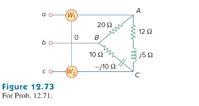
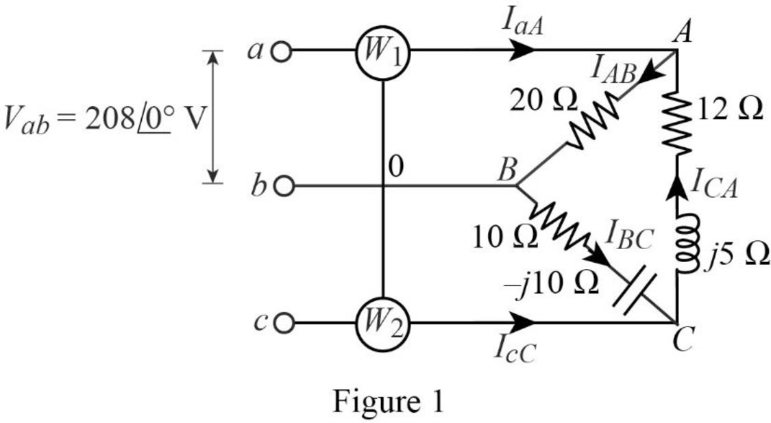
In Fig. 12.73, two wattmeters are properly connected to the unbalanced load supplied by a balanced source such that  with positive phase sequence.
- (a) Determine the reading of each wattmeter.
- (b) Calculate the total apparent power absorbed by the load.
(a)
Find the readings of wattmeter
Answer to Problem 71P
The readings of wattmeter
Explanation of Solution
Given data:
Refer to the Figure 12.73 in the textbook, which shows the unbalanced load circuit with two-wattmeters.
The balanced source connected the circuit has the line to line voltage
Formula used:
Consider the positive phase sequence.
Write the expression to find the line to line voltage
Here,
Write the expression to find the line to line voltage
Write the expression to find the line to line current
Here,
Write the expression to find the line to line to current
Here,
Write the expression to find the line to line current
Here,
Write the expression to find the line current
Write the expression to find the line current
Write the expression to find the power
Here,
Write the expression to find the power
Here,
Calculation:
The magnitude of the phase voltage
Substitute
Substitute
Substitute
Substitute
Substitute
Substitute
Substitute
Substitute
Write the expression to find the voltage
Substitute
Substitute
Conclusion:
Thus, the readings of wattmeter
(b)
Find the total apparent power absorbed by the unbalanced load.
Answer to Problem 71P
The total apparent power absorbed by the unbalanced load is
Explanation of Solution
Formula used:
Write the expression to find the total real power is,
Here,
Write the expression to find the total reactive power is,
Write the expression to find the total complex power is,
Write the expression to find the magnitude of the total apparent power is,
Here,
Calculation:
Substitute
Substitute
Substitute
Substitute
Conclusion:
Thus, the total apparent power absorbed by the unbalanced load is
Want to see more full solutions like this?
Chapter 12 Solutions
EE 98: Fundamentals of Electrical Circuits - With Connect Access


- Find Vfinal when Vs up and Vs V. Which LED will light in each case? Red or Green? Justify your answers. Fill the table below. Vs 8 ΚΩ Vos Χρι + 3 ΚΩ www 6 ΚΩ ww 4 ΚΩ Yo www Vo Vec-12 V Nol V final Vm w 3 ΚΩ 5 V 38 ΚΩ R= 1 kQ V -12 V Red LED Green LED Vs Vo Vfinal Which LED is ON? Varrow_forwardCircuits help please solve and explain. Question in images providedarrow_forward+ V 6.2 A 1.2 A S R 4 Ω Find the source voltage Vs 0.8 Aarrow_forward
- Determine i(t) for t≥ 0 given that the circuit below had been in steady state for a long time prior to t = 0. Also, I₁ = 1 5 A, R₁ =22, R2 =10 Q2, R3 = 32, R4 =7 2, and L=0.15 H. Also fill the table. m L ww R2 t = 0 R₁ 29 R3 R4 Time 0 iL(t) 0 8arrow_forwardPlease help explain this problemarrow_forward+ P = 16 W w w P = 8 W I R₁ R2 E = RT=322 1- Determine R1, R2, E ΙΩarrow_forward
- + 30 V = - 20 V + R 2- Use KVL to find the voltage V - V + + 8 Varrow_forwardFind the Thévenin equivalent circuit for the portions of the networks in Figure external to the elements between points a and b. a R₁ 2002 I = 0.1 A 0° Xc : 32 Ω R2 = 6802 20 Ω фъarrow_forwardFind the Norton equivalent circuit for the network external to the elements between a and b for the networks in Figure. E1 = 120 V Z 0° R ww 10 Ω Xc XL · 000 802 802 ① I = 0.5 AZ 60° ZL barrow_forward
- Using superposition, determine the current through inductance XL for each network in Figure I = 0.3 A 60° XL 000 802 XC 502 Ω E 10 V0° =arrow_forwardFind the Thévenin equivalent circuit for the portions of the networks in Figure external to the elements between points a and b. E = 20 VZ0° + R ww 2 ΚΩ Хо XL 000 6ΚΩ 3 ΚΩ b RLarrow_forwardWhat percentage of the full-load current of a thermally protected continuous-duty motor of more than one Hp can the trip current be, if the full-load current is 15 amperes? Ο 122 Ο 140 156 O 170arrow_forward
 Power System Analysis and Design (MindTap Course ...Electrical EngineeringISBN:9781305632134Author:J. Duncan Glover, Thomas Overbye, Mulukutla S. SarmaPublisher:Cengage Learning