
Concept explainers
Videos
In the braking test of a sports car, its velocity is reduced from 70 mi/h to zero in a distance of 170 ft with slipping impending. Knowing that the coefficient of kinetic friction is 80 percent of the coefficient of static friction, determine (a) the coefficient of static friction, (b) the stopping distance for the same initial velocity if the car skids. Ignore air resistance and rolling resistance.
(a)
Find the coefficient of static friction.
Answer to Problem 12.122RP
The coefficient of static friction is
Explanation of Solution
Given information:
The initial velocity
The final velocity (v) of the sports car is 0.
The distance
Calculation:
Write the general equation of weight of the car (W).
Here, m is the mass of the car and g is the acceleration due to gravity.
Sketch the free body diagram and kinetic diagram of the sports car as shown in Figure (1).
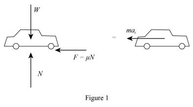
Refer Figure (1).
Consider the vertical equilibrium.
Here, N is the normal force on the car.
Substitute mg for W.
Substitute
Find the deceleration of the car using the equation:
Substitute 0 for v, 70 mi/h for
Apply coefficient of static friction for braking without skidding.
Refer Figure 1.
Find the coefficient of static friction.
Substitute 32.2m for N and
Thus, the coefficient of static friction is
(b)
Find the stopping distance for the same initial velocity if the car skids.
Answer to Problem 12.122RP
The stopping distance for the same initial velocity if the car skids is
Explanation of Solution
Given information:
The coefficient of kinetic friction is 80 percent of the coefficient of static friction.
Calculation:
Find the coefficient of kinetic friction using the equation:
Substitute 0.963 for
Apply coefficient of kinetic friction for braking with skidding.
Refer Figure (1).
Find the deceleration of the sports car
Substitute 0.7704 for
The deceleration is constant.
Find the stopping distance for the same initial velocity if the car skids using the equation:
Substitute 0 for v, 70 mi/h for
Thus, the stopping distance for the same initial velocity if the car skids is
Want to see more full solutions like this?
Chapter 12 Solutions
Vector Mechanics for Engineers: Statics and Dynamics
Additional Engineering Textbook Solutions
Mechanics of Materials (10th Edition)
Modern Database Management
Thermodynamics: An Engineering Approach
Automotive Technology: Principles, Diagnosis, And Service (6th Edition) (halderman Automotive Series)
Electric Circuits. (11th Edition)
Database Concepts (8th Edition)


- state is Derive an expression for the volume expansivity of a substance whose equation of RT P = v-b a v(v + b)TZ where a and b are empirical constants.arrow_forwardFor a gas whose equation of state is P(v-b)=RT, the specified heat difference Cp-Cv is equal to which of the following (show all work): (a) R (b) R-b (c) R+b (d) 0 (e) R(1+v/b)arrow_forwardof state is Derive an expression for the specific heat difference of a substance whose equation RT P = v-b a v(v + b)TZ where a and b are empirical constants.arrow_forward
- Temperature may alternatively be defined as T = ди v Prove that this definition reduces the net entropy change of two constant-volume systems filled with simple compressible substances to zero as the two systems approach thermal equilibrium.arrow_forwardUsing the Maxwell relations, determine a relation for equation of state is (P-a/v²) (v−b) = RT. Os for a gas whose av Tarrow_forward(◉ Homework#8arrow_forwardHomework#8arrow_forwardBox A has a mass of 15 kilograms and is attached to the 20 kilogram Box B using the cord and pulley system shown. The coefficient of kinetic friction between the boxes and surface is 0.2 and the moment of inertia of the pulley is 0.5 kg * m^ 2. After 2 seconds, how far do the boxes move? A бро Barrow_forwardBox A has a mass of 15 kilograms and is attached to the 20 kilogram Box B using the cord and pulley system shown. The coefficient of kinetic friction between the boxes and surface is 0.2 and the moment of inertia of the pulley is 0.5 kg * m^2. Both boxes are 0.25 m long and 0.25 m high. The cord is attached to the bottom of Box A and the middle of box B. After 2 seconds, how far do the boxes move? A From бро Barrow_forwardHomework#8arrow_forwardSign in PDF Lecture W09.pdf PDF MMB241 - Tutorial L9.pdf File C:/Users/KHULEKANI/Desktop/mmb241/MMB241%20-%20Tutorial%20L9.pdf II! Draw | I│Alla | Ask Copilot + of 4 D Topic: Kinetics of Particles: - Forces in dynamic system, Free body diagram, newton's laws of motion, and equations of motion. TQ1. The 10-kg block is subjected to the forces shown. In each case, determine its velocity when t=2s if v 0 when t=0 500 N F = (201) N 300 N (b) TQ2. The 10-kg block is subjected to the forces shown. In each case, determine its velocity at s-8 m if v = 3 m/s at s=0. Motion occurs to the right. 40 N F = (2.5 s) N 200 N 30 N (b) TQ3. Determine the initial acceleration of the 10-kg smooth collar. The spring has an unstretched length of 1 m. 1 σ Q ☆ Q 6 ا الى ☑arrow_forwardSign in PDF Lecture W09.pdf PDF MMB241 - Tutorial L9.pdf File C:/Users/KHULEKANI/Desktop/mmb241/MMB241%20-%20Tutorial%20L9.pdf II! Draw | I│Alla | Ask Copilot + 4 of 4 | D TQ9. If motor M exerts a force of F (10t 2 + 100) N determine the velocity of the 25-kg crate when t kinetic friction between the crate and the plane are μs The crate is initially at rest. on the cable, where t is in seconds, 4s. The coefficients of static and 0.3 and μk = 0.25, respectively. M 3 TQ10. The spring has a stiffness k = 200 N/m and is unstretched when the 25-kg block is at A. Determine the acceleration of the block when s = 0.4 m. The contact surface between the block and the plane is smooth. 0.3 m F= 100 N F= 100 N k = 200 N/m σ Q Q ☆ ا الى 6 ☑arrow_forwardarrow_back_iosSEE MORE QUESTIONSarrow_forward_iosRecommended textbooks for you
 Elements Of ElectromagneticsMechanical EngineeringISBN:9780190698614Author:Sadiku, Matthew N. O.Publisher:Oxford University Press
 Mechanics of Materials (10th Edition)Mechanical EngineeringISBN:9780134319650Author:Russell C. HibbelerPublisher:PEARSON
 Thermodynamics: An Engineering ApproachMechanical EngineeringISBN:9781259822674Author:Yunus A. Cengel Dr., Michael A. BolesPublisher:McGraw-Hill Education
 Control Systems EngineeringMechanical EngineeringISBN:9781118170519Author:Norman S. NisePublisher:WILEY
 Mechanics of Materials (MindTap Course List)Mechanical EngineeringISBN:9781337093347Author:Barry J. Goodno, James M. GerePublisher:Cengage Learning
 Engineering Mechanics: StaticsMechanical EngineeringISBN:9781118807330Author:James L. Meriam, L. G. Kraige, J. N. BoltonPublisher:WILEY
Elements Of ElectromagneticsMechanical EngineeringISBN:9780190698614Author:Sadiku, Matthew N. O.Publisher:Oxford University PressMechanics of Materials (10th Edition)Mechanical EngineeringISBN:9780134319650Author:Russell C. HibbelerPublisher:PEARSONThermodynamics: An Engineering ApproachMechanical EngineeringISBN:9781259822674Author:Yunus A. Cengel Dr., Michael A. BolesPublisher:McGraw-Hill EducationControl Systems EngineeringMechanical EngineeringISBN:9781118170519Author:Norman S. NisePublisher:WILEYMechanics of Materials (MindTap Course List)Mechanical EngineeringISBN:9781337093347Author:Barry J. Goodno, James M. GerePublisher:Cengage LearningEngineering Mechanics: StaticsMechanical EngineeringISBN:9781118807330Author:James L. Meriam, L. G. Kraige, J. N. BoltonPublisher:WILEY