
EBK MECHANICS OF MATERIALS
7th Edition
ISBN: 8220100257063
Author: BEER
Publisher: YUZU
expand_more
expand_more
format_list_bulleted
Videos
Textbook Question
Chapter 11.3, Problem 27P
11.24 through 11.27 Taking into account only the effect of normal stresses, determine the strain energy of the prismatic beam AB for the loading shown.
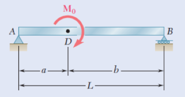
Fig. P11.27
Expert Solution & Answer

Trending nowThis is a popular solution!

Students have asked these similar questions
Quiz/An eccentrically loaded bracket is welded to the support as shown in Figure below. The load is static. The weld size
for weld w1 is h1 = 4mm, for w2 h2 = 6mm, and for w3 is h3 -6.5 mm. Determine the safety factor (S.f) for the welds.
F=29 kN. Use an AWS Electrode type (E100xx).
BES FOR P
163 mm
133 mm
140 mm
Example
-4s
F(s) =
=
(s²+4)²
As + B Cs+D
+
(s²+4) (s²+4)²
(s²+4)
(H.W)
Q1/ Find L[t et sin t]
Q2/ Find The Laplace Transform
f(t) = [sint
[sint 0
Chapter 11 Solutions
EBK MECHANICS OF MATERIALS
Ch. 11.3 - Determine the modulus of resilience for each of...Ch. 11.3 - Determine the modulus of resilience for each of...Ch. 11.3 - Determine the modulus of resilience for each of...Ch. 11.3 - Determine the modulus of resilience for each of...Ch. 11.3 - The stress-strain diagram shown has been drawn...Ch. 11.3 - The stress-strain diagram shown has been drawn...Ch. 11.3 - Prob. 7PCh. 11.3 - Prob. 8PCh. 11.3 - Using E = 29 106 psi, determine (a) the strain...Ch. 11.3 - Using E = 200 GPa, determine (a) the strain energy...
Ch. 11.3 - A 30-in. length of aluminum pipe of...Ch. 11.3 - A single 6-mm-diameter steel pin B is used to...Ch. 11.3 - Prob. 13PCh. 11.3 - Prob. 14PCh. 11.3 - The assembly ABC is made of a steel for which E =...Ch. 11.3 - Show by integration that the strain energy of the...Ch. 11.3 - Prob. 17PCh. 11.3 - Prob. 18PCh. 11.3 - Prob. 19PCh. 11.3 - 11.18 through 11.21 In the truss shown, all...Ch. 11.3 - Prob. 21PCh. 11.3 - Each member of the truss shown is made of aluminum...Ch. 11.3 - Each member of the truss shown is made of aluminum...Ch. 11.3 - 11.24 through 11.27 Taking into account only the...Ch. 11.3 - Prob. 25PCh. 11.3 - 11.24 through 11.27 Taking into account only the...Ch. 11.3 - 11.24 through 11.27 Taking into account only the...Ch. 11.3 - Prob. 28PCh. 11.3 - Prob. 29PCh. 11.3 - Prob. 30PCh. 11.3 - 11.30 and 11.31 Using E = 200 GPa, determine the...Ch. 11.3 - Assuming that the prismatic beam AB has a...Ch. 11.3 - Prob. 33PCh. 11.3 - The design specifications for the steel shaft AB...Ch. 11.3 - Show by integration that the strain energy in the...Ch. 11.3 - The state of stress shown occurs in a machine...Ch. 11.3 - Prob. 37PCh. 11.3 - The state of stress shown occurs in a machine...Ch. 11.3 - Prob. 39PCh. 11.3 - Prob. 40PCh. 11.3 - Prob. 41PCh. 11.5 - A 5-kg collar D moves along the uniform rod AB and...Ch. 11.5 - The 18-lb cylindrical block E has a horizontal...Ch. 11.5 - The cylindrical block E has a speed v0 =16 ft/s...Ch. 11.5 - Prob. 45PCh. 11.5 - Prob. 46PCh. 11.5 - The 48-kg collar G is released from rest in the...Ch. 11.5 - Prob. 48PCh. 11.5 - Prob. 49PCh. 11.5 - Prob. 50PCh. 11.5 - Prob. 51PCh. 11.5 - The 2-kg block D is dropped from the position...Ch. 11.5 - The 10-kg block D is dropped from a height h = 450...Ch. 11.5 - Prob. 54PCh. 11.5 - A 160-lb diver jumps from a height of 20 in. onto...Ch. 11.5 - Prob. 56PCh. 11.5 - A block of weight W is dropped from a height h...Ch. 11.5 - 11.58 and 11.59 Using the method of work and...Ch. 11.5 - 11.58 and 11.59 Using the method of work and...Ch. 11.5 - 11.60 and 11.61 Using the method of work and...Ch. 11.5 - 11.60 and 11.61 Using the method of work and...Ch. 11.5 - 11.62 and 11.63 Using the method of work and...Ch. 11.5 - 11.62 and 11.63 Using the method of work and...Ch. 11.5 - Using the method of work and energy, determine the...Ch. 11.5 - Using the method of work and energy, determine the...Ch. 11.5 - The 20-mm diameter steel rod BC is attached to the...Ch. 11.5 - Torques of the same magnitude T are applied to the...Ch. 11.5 - Prob. 68PCh. 11.5 - The 20-mm-diameter steel rod CD is welded to the...Ch. 11.5 - The thin-walled hollow cylindrical member AB has a...Ch. 11.5 - 11.71 and 11.72 Each member of the truss shown has...Ch. 11.5 - 11.71 and 11.72 Each member of the truss shown has...Ch. 11.5 - Each member of the truss shown is made of steel...Ch. 11.5 - Each member of the truss shown is made of steel....Ch. 11.5 - Each member of the truss shown is made of steel...Ch. 11.5 - The steel rod BC has a 24-mm diameter and the...Ch. 11.9 - 11.77 and 11.78 Using the information in Appendix...Ch. 11.9 - 11.77 and 11.78 Using the information in Appendix...Ch. 11.9 - 11.79 through 11.82 For the beam and loading...Ch. 11.9 - 11.79 through 11.82 For the beam and loading...Ch. 11.9 - 11.79 through 11.82 For the beam and loading...Ch. 11.9 - 11.79 through 11.82 For the beam and loading...Ch. 11.9 - 11.83 through 11.85 For the prismatic beam shown,...Ch. 11.9 - 11.83 through 11.85 For the prismatic beam shown,...Ch. 11.9 - 11.83 through 11.85 For the prismatic beam shown,...Ch. 11.9 - 11.86 through 11.88 For the prismatic beam shown,...Ch. 11.9 - 11.86 through 11.88 For the prismatic beam shown,...Ch. 11.9 - 11.86 through 11.88 For the prismatic beam shown,...Ch. 11.9 - For the prismatic beam shown, determine the slope...Ch. 11.9 - For the prismatic beam shown, determine the slope...Ch. 11.9 - For the beam and loading shown, determine the...Ch. 11.9 - For the beam and loading shown, determine the...Ch. 11.9 - 11.93 and 11.94 For the beam and loading shown,...Ch. 11.9 - 11.93 and 11.94 For the beam and loading shown,...Ch. 11.9 - For the beam and loading shown, determine the...Ch. 11.9 - For the beam and loading shown, determine the...Ch. 11.9 - Prob. 97PCh. 11.9 - For the beam and loading shown, determine the...Ch. 11.9 - 11.99 and 11.100 For the truss and loading shown,...Ch. 11.9 - 11.99 and 11.100 For the truss and loading shown,...Ch. 11.9 - 11.101 and 11.102 Each member of the truss shown...Ch. 11.9 - 11.101 and 11.102 Each member of the truss shown...Ch. 11.9 - 11.103 and 11.104 Each member of the truss shown...Ch. 11.9 - 11.103 and 11 104 Each member of the truss shown...Ch. 11.9 - A uniform rod of flexural rigidity EI is bent and...Ch. 11.9 - For the uniform rod and loading shown and using...Ch. 11.9 - For the beam and loading shown and using...Ch. 11.9 - Two rods AB and BC of the same flexural rigidity...Ch. 11.9 - Three rods, each of the same flexural rigidity EI,...Ch. 11.9 - Three rods, each of the same flexural rigidity EI,...Ch. 11.9 - 11.111 through 11.115 Determine the reaction at...Ch. 11.9 - 11.111 through 11.115 Determine the reaction at...Ch. 11.9 - 11.111 through 11.115 Determine the reaction at...Ch. 11.9 - 11.111 through 11.115 Determine the reaction at...Ch. 11.9 - 11.111 through 11.115 Determine the reaction at...Ch. 11.9 - For the uniform beam and loading shown, determine...Ch. 11.9 - 11.117 through 11.120 Three members of the same...Ch. 11.9 - 11.117 through 11.120 Three members of the same...Ch. 11.9 - 11.117 through 11.120 Three members of the same...Ch. 11.9 - 11.117 through 11.120 Three members of the same...Ch. 11.9 - 11.121 and 11.122 Knowing that the eight members...Ch. 11.9 - 11.121 and 11.122 Knowing that the eight members...Ch. 11 - Rod AB is made of a steel for which the yield...Ch. 11 - Each member of the truss shown is made of steel...Ch. 11 - The ship at A has just started to drill for oil on...Ch. 11 - Collar D is released from rest in the position...Ch. 11 - Each member of the truss shown is made of steel...Ch. 11 - A block of weight W is placed in contact with a...Ch. 11 - Two solid steel shafts are connected by the gears...Ch. 11 - A 160-lb diver jumps from a height of 20 in. onto...Ch. 11 - For the prismatic beam shown, determine the slope...Ch. 11 - A disk of radius a has been welded to end B of the...Ch. 11 - A uniform rod of flexural rigidity EI is bent and...Ch. 11 - The steel bar ABC has a square cross section of...
Knowledge Booster


Learn more about
Need a deep-dive on the concept behind this application? Look no further. Learn more about this topic, mechanical-engineering and related others by exploring similar questions and additional content below.Similar questions
- b) The 50 mm diameter rod is placed in a hole, lubricated walls. There is no clearance between the rod and the sides of the hole. Determine the change in length of the rod if an 8 kN load is applied. Take E(brass) = 80 GPa; v = 0.55 [10] 50 mmm 300 rat 3arrow_forwardThe Mach number NM for flow of a perfect gas in a pipe depends upon the specific-heat ratio k (dimensionless), the pressure p, the density ρ, and the velocity V. Obtain by dimensional reasoning the form of the Mach number expression. (Buckingham pi)Answer: NM = f(V/sqrt(p/ρ), k)arrow_forwardoyfr 3. The figure shows a frame under the influence of an external loading made up of five forces and two moments. Use the scalar method to calculate moments. a. Write the resultant force of the external loading in Cartesian vector form. b. Determine the & direction of the resultant moment of the external loading about A. 15 cm 18 cm 2.2 N-m B 50 N 45° 10 cm 48 N.m 250 N 60 N 20 21 50 N 25 cm 100 N A 118, 27cm 5, 4:1arrow_forward
- Assume the Link AO is the input and revolves 360°, determine a. the coordinates of limit positions of point B, b. the angles (AOC) corresponding to the limit positionsarrow_forwardoyfr 3. The figure shows a frame under the influence of an external loading made up of five forces and two moments. Use the scalar method to calculate moments. a. Write the resultant force of the external loading in Cartesian vector form. b. Determine the & direction of the resultant moment of the external loading about A. 15 cm 18 cm 2.2 N-m B 50 N 45° 10 cm 48 N.m 250 N 60 N 20 21 50 N 25 cm 100 N A 118, 27cm 5, 4:1arrow_forwardThe 2-mass system shown below depicts a disk which rotates about its center and has rotational moment of inertia Jo and radius r. The angular displacement of the disk is given by 0. The spring with constant k₂ is attached to the disk at a distance from the center. The mass m has linear displacement & and is subject to an external force u. When the system is at equilibrium, the spring forces due to k₁ and k₂ are zero. Neglect gravity and aerodynamic drag in this problem. You may assume the small angle approximation which implies (i) that the springs and dampers remain in their horizontal / vertical configurations and (ii) that the linear displacement d of a point on the edge of the disk can be approximated by d≈re. Ө K2 www m 4 Cz 777777 Jo Make the following assumptions when analyzing the forces and torques: тв 2 0>0, 0>0, x> > 0, >0 Derive the differential equations of motion for this dynamic system. Start by sketching LARGE and carefully drawn free-body-diagrams for the disk and the…arrow_forward
- A linear system is one that satisfies the principle of superposition. In other words, if an input u₁ yields the output y₁, and an input u2 yields the output y2, the system is said to be linear if a com- bination of the inputs u = u₁ + u2 yield the sum of the outputs y = y1 + y2. Using this fact, determine the output y(t) of the following linear system: given the input: P(s) = = Y(s) U(s) = s+1 s+10 u(t) = e−2+ sin(t) =earrow_forwardThe manometer fluid in the figure given below is mercury where D = 3 in and h = 1 in. Estimate the volume flow in the tube (ft3/s) if the flowing fluid is gasoline at 20°C and 1 atm. The density of mercury and gasoline are 26.34 slug/ft3 and 1.32 slug/ft3 respectively. The gravitational force is 32.2 ft/s2.arrow_forwardUsing the Bernoulli equation to find the general solution. If an initial condition is given, find the particular solution. y' + xy = xy¯¹, y(0) = 3arrow_forward
- Test for exactness. If exact, solve. If not, use an integrating factor as given or obtained by inspection or by the theorems in the text. a. 2xydx+x²dy = 0 b. (x2+y2)dx-2xydy = 0 c. 6xydx+5(y + x2)dy = 0arrow_forwardNewton's law of cooling. A thermometer, reading 5°C, is brought into a room whose temperature is 22°C. One minute later the thermometer reading is 12°C. How long does it take until the reading is practically 22°C, say, 21.9°C?arrow_forwardSolve a. y' + 2xy = ex-x² b. y' + y sin x = ecosx, y(0) = −1 y(0) = −2.5arrow_forward
arrow_back_ios
SEE MORE QUESTIONS
arrow_forward_ios
Recommended textbooks for you
 Elements Of ElectromagneticsMechanical EngineeringISBN:9780190698614Author:Sadiku, Matthew N. O.Publisher:Oxford University Press
 Mechanics of Materials (10th Edition)Mechanical EngineeringISBN:9780134319650Author:Russell C. HibbelerPublisher:PEARSON
 Thermodynamics: An Engineering ApproachMechanical EngineeringISBN:9781259822674Author:Yunus A. Cengel Dr., Michael A. BolesPublisher:McGraw-Hill Education
 Control Systems EngineeringMechanical EngineeringISBN:9781118170519Author:Norman S. NisePublisher:WILEY
 Mechanics of Materials (MindTap Course List)Mechanical EngineeringISBN:9781337093347Author:Barry J. Goodno, James M. GerePublisher:Cengage Learning
 Engineering Mechanics: StaticsMechanical EngineeringISBN:9781118807330Author:James L. Meriam, L. G. Kraige, J. N. BoltonPublisher:WILEY
Elements Of Electromagnetics
Mechanical Engineering
ISBN:9780190698614
Author:Sadiku, Matthew N. O.
Publisher:Oxford University Press
Mechanics of Materials (10th Edition)
Mechanical Engineering
ISBN:9780134319650
Author:Russell C. Hibbeler
Publisher:PEARSON
Thermodynamics: An Engineering Approach
Mechanical Engineering
ISBN:9781259822674
Author:Yunus A. Cengel Dr., Michael A. Boles
Publisher:McGraw-Hill Education
Control Systems Engineering
Mechanical Engineering
ISBN:9781118170519
Author:Norman S. Nise
Publisher:WILEY
Mechanics of Materials (MindTap Course List)
Mechanical Engineering
ISBN:9781337093347
Author:Barry J. Goodno, James M. Gere
Publisher:Cengage Learning
Engineering Mechanics: Statics
Mechanical Engineering
ISBN:9781118807330
Author:James L. Meriam, L. G. Kraige, J. N. Bolton
Publisher:WILEY
An Introduction to Stress and Strain; Author: The Efficient Engineer;https://www.youtube.com/watch?v=aQf6Q8t1FQE;License: Standard YouTube License, CC-BY