
Videos
Consider a two-stage compression refrigeration system operating between the pressure limits of 1.4 and 0.12 MPa. The working fluid is refrigerant-134a. The refrigerant leaves the condenser as a saturated liquid and is throttled to a flash chamber operating at 0.5 MPa. Part of the refrigerant evaporates during this flashing process, and this vapor is mixed with the refrigerant leaving the low-pressure compressor. The mixture is then compressed to the condenser pressure by the high-pressure compressor. The liquid in the flash chamber is throttled to the evaporator pressure, and it cools the refrigerated space as it vaporizes in the evaporator. Assuming the refrigerant leaves the evaporator as saturated vapor and both compressors are isentropic, determine (a) the fraction of the refrigerant that evaporates as it is throttled to the flash chamber, (b) the amount of heat removed from the refrigerated space and the compressor work per unit mass of refrigerant flowing through the condenser, and (c) the coefficient of performance.
(a)
The fraction of the refrigerant that evaporates as it is throttled to the flash chamber.
Answer to Problem 113RP
The fraction of the refrigerant that evaporates as it is throttled to the flash chamber is
Explanation of Solution
Show the T-s diagram as in Figure (1).
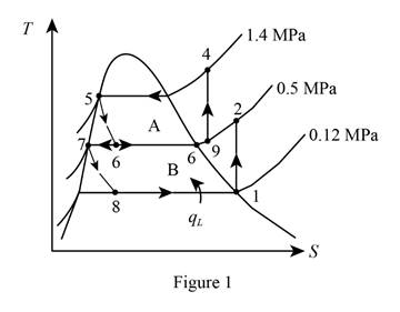
From Figure (1), write the specific enthalpy at state 5 is equal to state 6 due to throttling process.
Here, specific enthalpy at state 5 and 6 is
From Figure (1), write the specific enthalpy at state 7 is equal to state 8 due to throttling process.
Here, specific enthalpy at state 7 and 8 is
Express the fraction of the refrigerant that evaporates as it is throttled to the flash chamber
Here, specific enthalpy at saturated vapor is
Conclusion:
Perform unit conversion of pressure at state 1 from
Refer Table A-12, “saturated refrigerant-134a-pressure table”, and write the properties corresponding to pressure at state 1
Here, specific entropy and enthalpy at state 1 is
Refer Table A-13, “superheated refrigerant 134a”, and write the specific enthalpy at state 2 corresponding to pressure at state 2 of
Write the formula of interpolation method of two variables.
Here, the variables denote by x and y is specific entropy at state 2 and specific enthalpy at state 2 respectively.
Show the specific enthalpy at state 2 corresponding to specific entropy as in Table (1).
|
Specific entropy at state 2 |
Specific enthalpy at state 2 |
| 0.9384 | 263.48 |
| 0.94789 | |
| 0.9704 | 273.03 |
Substitute
Thus, the specific enthalpy at state 2 is,
Perform unit conversion of pressure at state 3 from
Refer Table A-12, “saturated refrigerant-134a-pressure table”, and write the property corresponding to pressure at state 3
Perform unit conversion of pressure at state 5 from
Refer Table A-12, “saturated refrigerant-134a-pressure table”, and write the property corresponding to pressure at state 5
Here, specific enthalpy at saturated liquid is
Substitute
Refer Table A-12, “saturated refrigerant-134a-pressure table”, and write the property corresponding to pressure at state 8
Substitute
Refer Table A-12, “saturated refrigerant-134a-pressure table”, and write the specific enthalpy at evaporation and pressure of
Substitute
Hence, the fraction of the refrigerant that evaporates as it is throttled to the flash chamber is
(b)
The amount of heat removed from the refrigerated space and the compressor work per unit mass of refrigerant flowing through the condenser.
Answer to Problem 113RP
The amount of heat removed from the refrigerated space is
Explanation of Solution
Express the enthalpy at state 9 by using an energy balance on the mixing chamber.
Here, the rate of total energy entering the system is
Express the amount of heat removed from the refrigerated space.
Express the compressor work per unit mass of refrigerant flowing through the condenser.
Conclusion:
Substitute
Refer Table A-13, “superheated refrigerant 134a”, and write the specific entropy at state 9 corresponding to pressure at state 9 of
Show the specific enthropy at state 9 corresponding to specific enthalpy as in Table (2).
|
Specific enthalpy at state 9 |
Specific entropy at state 9 |
| 263.48 | 0.9384 |
| 264.28 | |
| 273.03 | 0.9704 |
Use excels and tabulates the values of Table (2) in Equation (IV) to get,
Thus, the specific entropy at state 9 is,
Refer Table A-13, “superheated refrigerant 134a”, and write the specific enthalpy at state 4 corresponding to pressure at state 4 of
Substitute
Hence, the amount of heat removed from the refrigerated space is
Substitute
Hence, the compressor work per unit mass of refrigerant flowing through the condenser is
(c)
The coefficient of performance of the system.
Answer to Problem 113RP
The coefficient of performance of the system is
Explanation of Solution
Express the coefficient of performance of the system.
Conclusion:
Substitute
Hence, the coefficient of performance of the system is
Want to see more full solutions like this?
Chapter 11 Solutions
EBK THERMODYNAMICS: AN ENGINEERING APPR


- Correct Answer is written below. Detailed and complete fbd only please. I will upvote, thank you. 1: The assembly shown is composed of a rigid plank ABC, supported by hinge at A, spring at B and cable at C.The cable is attached to a frictionless pulley at D and rigidly supported at E. The cable is made of steel with E = 200,000MPa and cross-sectional area of 500 mm2. The details of pulley at D is shown. The pulley is supported by a pin, passingthough the pulley and attached to both cheeks. Note that E is directly above B.Given: H = 3 m; L1 = 2 m; L2 = 4 m; w = 12 kN/m; x:y = 3:4Spring Parameters:Wire diameter = 30 mmMean Radius = 90 mmNumber of turns = 12Modulus of Rigidity = 80 GPaAllowable stresses:Allowable shear stress of Pin at D = 85 MPaAllowable normal stress of cheek at D = 90MPaAllowable bearing stress of cheek at D = 110MPa1. Calculate the reaction of spring Band tension in cable at C.2. Calculate the vertical displacementat C and the required diameter ofpin at D.3.…arrow_forwardCorrect answer and complete fbd only. I will upvote. The compound shaft, composed of steel,aluminum, and bronze segments, carries the two torquesshown in the figure. If TC = 250 lb-ft, determine the maximumshear stress developed in each material (in ksi). The moduliof rigidity for steel, aluminum, and bronze are 12 x 106 psi, 4x 10⁶ psi, and 6 x 10⁶ psi, respectivelyarrow_forwardCan you explain the algebra steps that aren't shown but stated to be there, on how to get this equationarrow_forward
- Correct answer and complete fbd only. I will upvote. A flanged bolt coupling consists of two concentric rows of bolts. The inner row has 6 nos. of 16mm diameterbolts spaced evenly in a circle of 250mm in diameter. The outer row of has 10 nos. of 25 mm diameter bolts spaced evenly in a circle of 500mm in diameter. If the allowable shear stress on one bolt is 60 MPa, determine the torque capacity of the coupling. The Poisson’s ratio of the inner row of bolts is 0.2 while that of the outer row is 0.25 and the bolts are steel, E =200 GPa.arrow_forwardCorrect answer and complete fbd only. I will upvote. 10: The constant wall thickness of a steel tube with the cross sectionshown is 2 mm. If a 600-N-m torque is applied to the tube. Use G = 80 GPa forsteel.1. Find the shear stress (MPa) in the wall of the tube.2. Find the angle of twist, in degrees per meter of length.arrow_forwardCORRECT ANSWER WITH COMPLETE FBD ONLY. I WILL UPVOTE. A torque wrench is used to tighten the pipe shown.Dimensions: S1 = 400 mm; S2 = 250 mm; S3 = 100 mmModulus of Rigidity G = 78 GPa1. The diameter of the solid pipe is 20 mm. How much is themaximum force P (N) that can be applied based on theallowable shear stress of 60 MPa?2. For a hollow pipe with 50 mm outside diameter and is 6 mmthick, compute for the maximum force P (kN) that can beapplied such that the angle of twist at A does not exceed 5degrees.3. The torque applied to tighten the hollow pipe is 200 N-m.Given: Pipe outside diameter = 50 mm Pipe thickness = 6 mmSolve for the resulting maximum shear stress (MPa) in the pipe.arrow_forward
- Correct answer and complete fbd only. I will upvote. 6: The shaft carries a total torque T0 that is uniformly distributedover its length L. Determine the angle of twist (degrees) of the shaft in termsif T0 = 1.2 kN-m, L = 2 m, G = 80 GPa, and diameter = 120 mm.arrow_forward2. Calculate the force in all members of the trusses shown using the method of joints. A 5525 lb C 3500 lb BY 14'-0" D 10'- 0" 6250 lb 10'- 0" Earrow_forwardCorrect answer and complete fbd only. I will upvote. 8: The steel rod fits loosely inside the aluminum sleeve. Both components are attached to a rigid wall at A andjoined together by a pin at B. Because of a slight misalignmentof the pre-drilled holes, the torque T0 = 750 N-m was appliedto the steel rod before the pin could be inserted into theholes. Determine the torque (N-m) in each component afterT0 was removed. Use G = 80 GPa for steel and G = 28 GPa foraluminumarrow_forward
- Correct answer and complete fbd only. I will upvote. 9: The two steel shafts, each with one end builtinto a rigid support, have flanges attached to their freeends. The flanges are to be bolted together. However,initially there is a 6⁰ mismatch in the location of the boltholes as shown in the figure. Determine the maximumshear stress(ksi) in each shaft after the flanges have beenbolted together. The shear modulus of elasticity for steelis 12 x 106 psi. Neglect deformations of the bolts and theflanges.arrow_forwardCorrect answer and complete fbd only. I will upvote. The tapered, wrought iron shaft carriesthe torque T = 2000 lb-in at its free end. Determine theangle of twist (degrees) of the shaft. Use G = 10 x 106psi for wrought ironarrow_forwardCorrect answer and complete fbd only. I will upvote. The compound shaft, consisting of steel and aluminumsegments, carries the two torques shown in the figure. Determine themaximum permissible value of T subject to the following designconditions: τst ≤ 83 MPa, τal ≤ 55 MPa, and θ ≤ 6⁰ (θ is the angle ofrotation of the free end). Use G =83 GPa for steel and G = 28 GPa foraluminum.arrow_forward
 Refrigeration and Air Conditioning Technology (Mi...Mechanical EngineeringISBN:9781305578296Author:John Tomczyk, Eugene Silberstein, Bill Whitman, Bill JohnsonPublisher:Cengage Learning