
Videos
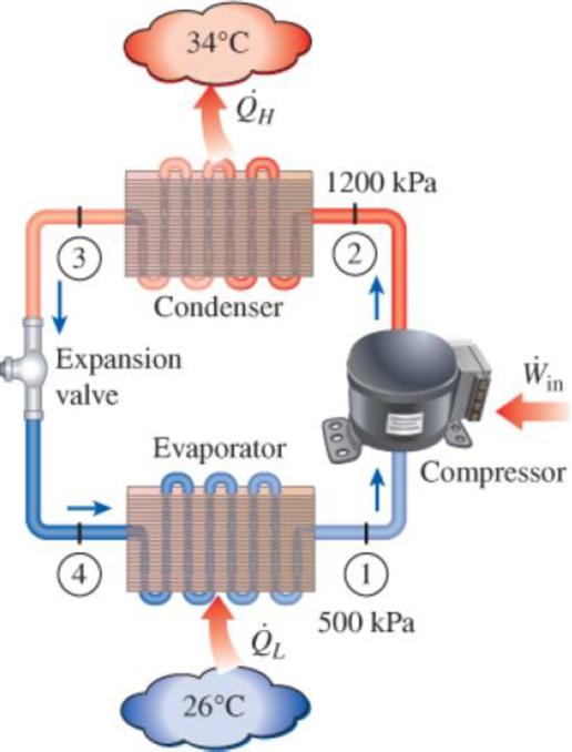
An air conditioner with refrigerant-134a as the working fluid is used to keep a room at 26°C by rejecting the waste heat to the outside air at 34°C. The room is gaining heat through the walls and the windows at a rate of 250 kJ/min while the heat generated by the computer, TV, and lights amounts to 900 W. An unknown amount of heat is also generated by the people in the room. The condenser and evaporator pressures are 1200 and 500 kPa, respectively. The refrigerant is saturated liquid at the condenser exit and saturated vapor at the compressor inlet. If the refrigerant enters the compressor at a rate of 100 L/min and the isentropic efficiency of the compressor is 75 percent, determine (a) the temperature of the refrigerant at the compressor exit, (b) the rate of heat generation by the people in the room, (c) the COP of the air conditioner, and (d) the minimum volume flow rate of the refrigerant at the compressor inlet for the same compressor inlet and exit conditions.
FIGURE P11–115
(a)
The temperature of the refrigerant at the compressor exit.
Answer to Problem 111RP
The temperature of the refrigerant at the compressor exit is
Explanation of Solution
Show the T-s diagram as in Figure (1).
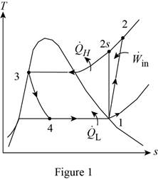
From Figure (1), write the specific enthalpy at state 3 is equal to state 4 due to throttling process.
Here, specific enthalpy at state 3 and 4 is
Express the specific enthalpy at state 2.
Here, specific enthalpy at state 2s is
Conclusion:
Perform the unit conversion of pressure at state 1 from
Refer Table A-13, “superheated refrigerant-134a”, and write the properties corresponding to pressure of
Here, specific enthalpy, volume and entropy is
Perform the unit conversion of pressure at state 2 from
Refer Table A-12, “saturated refrigerant-134a-pressure table”, and write the specific enthalpy at state 3 corresponding to pressure at state 3 of
Here, specific enthalpy at saturated liquid is
Substitute
Refer Table A-13, “superheated refrigerant 134a”, and write the specific enthalpy at state 2s corresponding to pressure at state 2 of
Write the formula of interpolation method of two variables.
Here, the variables denote by x and y is specific entropy at state 2 and specific enthalpy at state 2 respectively.
Show the specific enthalpy at state 2s corresponding to specific entropy as in Table (1).
|
Specific entropy at state 2 |
Specific enthalpy at state 2s |
| 0.9132 | 273.92 |
| 0.9242 | |
| 0.9268 | 278.28 |
Substitute
Thus, the specific enthalpy at state 2s is,
Substitute
Refer Table A-13, “superheated refrigerant 134a”, and write the temperature at state 2 corresponding to pressure at state 2 of
Show the temperature at state 2 corresponding to specific enthalpy at state 2 as in Table (2).
|
Specific enthalpy at state 2s |
Temperature at state 2 |
| 278.28 | 50 |
| 283.48 | |
| 289.66 | 60 |
Use excels and tabulates the values form Table (2) in Equation (III) to get,
Hence, the temperature of the refrigerant at the compressor exit is
(b)
The rate of heat generation by the people in the room.
Answer to Problem 111RP
The rate of heat generation by the people in the room is
Explanation of Solution
Express the mass flow rate of the refrigerant.
Here, volume flow rate at state 1 is
Express the refrigeration load.
Express the rate of heat generation by the people in the room.
Here, rate of heat generated is
Conclusion:
Substitute
Substitute
Substitute
Hence, the rate of heat generation by the people in the room is
(c)
The COP of the air conditioner.
Answer to Problem 111RP
The COP of the air conditioner is
Explanation of Solution
Express the rate of work input.
Express the coefficient of performance of the air conditioner.
Conclusion:
Substitute
Substitute
Hence, the COP of the air conditioner is
(d)
The minimum volume flow rate of the refrigerant at the compressor inlet.
Answer to Problem 111RP
The minimum volume flow rate of the refrigerant at the compressor inlet is
Explanation of Solution
Express the reversible coefficient of performance of the cycle.
Here, high and low temperature medium is
Express corresponding minimum power input.
Express the minimum mass flow rate.
Express the minimum volume flow rate of the refrigerant at the compressor inlet
Conclusion:
Substitute
Substitute
Substitute
Substitute
Hence, the minimum volume flow rate of the refrigerant at the compressor inlet is
Want to see more full solutions like this?
Chapter 11 Solutions
EBK THERMODYNAMICS: AN ENGINEERING APPR


- My ID# 016948724 please find the forces for Fx=0: fy=0: fz=0: please help me to solve this problem step by steparrow_forwardMy ID# 016948724 please solve the proble step by step find the forces fx=o: fy=0; fz=0; and find shear moment and the bending moment diagran please draw the diagram for the shear and bending momentarrow_forwardMy ID#016948724. Please help me to find the moment of inertia lx ly are a please show to solve step by stepsarrow_forward
- My ID# 016948724arrow_forwardPlease do not use any AI tools to solve this question. I need a fully manual, step-by-step solution with clear explanations, as if it were done by a human tutor. No AI-generated responses, please.arrow_forwardPlease do not use any AI tools to solve this question. I need a fully manual, step-by-step solution with clear explanations, as if it were done by a human tutor. No AI-generated responses, please.arrow_forward
- Please do not use any AI tools to solve this question. I need a fully manual, step-by-step solution with clear explanations, as if it were done by a human tutor. No AI-generated responses, please.arrow_forward[Q2]: The cost information supplied by the cost accountant is as follows:Sales 20,00 units, $ 10 per unitCalculate the (a/ newsale guantity and (b) new selling price to earn the sameVariable cost $ 6 per unit, Fixed Cost $ 30,000, Profit $ 50,000profit ifi) Variable cost increases by $ 2 per unitil) Fixed cost increase by $ 10,000Ili) Variable cost increase by $ 1 per unit and fixed cost reduces by $ 10,000arrow_forwardcan you please help me perform Visual Inspection and Fractography of the attatched image: Preliminary examination to identify the fracture origin, suspected fatigue striation, and corrosion evidences.arrow_forward
 Refrigeration and Air Conditioning Technology (Mi...Mechanical EngineeringISBN:9781305578296Author:John Tomczyk, Eugene Silberstein, Bill Whitman, Bill JohnsonPublisher:Cengage Learning
 Principles of Heat Transfer (Activate Learning wi...Mechanical EngineeringISBN:9781305387102Author:Kreith, Frank; Manglik, Raj M.Publisher:Cengage Learning