
Videos
The greatest amount of exergy destroyed among the processes of system.
Answer to Problem 117RP
The greatest amount of exergy destroyed among the processes of system is
Explanation of Solution
Sketch the schematic layout of the two-stage compression refrigeration system as in Figure (1).
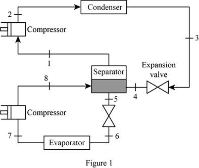
Sketch the
Write the relation between the specific enthalpies at the inlet and exit of throttling.
Here, specific enthalpy of the refrigerant at the inlet of throttling is
Write the energy balance equation for the separator.
Here, mass flow rate of the refrigerant at the end of high pressure compressor is
Write the expression to calculate the quality of the refrigerant
Here, specific enthalpy of the saturated liquid is
Write the expression to calculate the specific entropy for saturated refrigerant
Here, specific entropy of the saturated liquid is
Write the expression to calculate the rate of cooling produced
Here, specific enthalpy at the inlet of low pressure compressor is
Write the expression to calculate the rate of heat rejected from the system
Here, specific enthalpy at the exit of high pressure compressor is
Write the general expression to calculate the exergy destruction
Here, mass flow rate is
Conclusion:
From the Table A-11 of “Saturated refrigerant R-134a: Temperature”, obtain the properties of refrigerant at high pressure compressor inlet temperature
From the Table A-13 of “Superheated refrigerant R-134a”, obtain the specific enthalpy of high pressure compression exit at pressure
From the Table A-12 of “Saturated refrigerant R-134a: Pressure”, obtain the properties of refrigerant at high pressure cycle throttle inlet pressure of
Substitute
From the Table A-12 of “Saturated refrigerant R-134a: Pressure”, obtain the properties of refrigerant at high pressure cycle throttle exit temperature of
Substitute
Substitute
From the Table A-12 of “Saturated refrigerant R-134a: Pressure”, obtain the properties of refrigerant at low pressure cycle throttle inlet temperature of
Here, pressure of refrigerant at the separator is
Substitute
From the Table A-11 of “Saturated refrigerant R-134a: Temperature”, obtain the properties of refrigerant at low pressure expansion valve exit temperature
Substitute
Substitute 0.2437 for
From the Table A-11 of “Saturated refrigerant R-134a: Temperature”, obtain the properties of refrigerant at low pressure compressor inlet temperature
From the Table A-13 of “Superheated refrigerant R-134a”, obtain the specific enthalpy of low pressure compression exit at pressure
Substitute
Substitute
Substitute
Rewrite the Equation (VII) for the process 2 to 3.
Here, the temperature of the high temperature reservoir is
Substitute
Rewrite the Equation (VII) for the process 3 to 4.
Substitute
Rewrite the Equation (VII) for the process 5 to 6.
Substitute
Rewrite the Equation (VII) for the process 6 to 7.
Substitute
Rewrite the Equation (VII) for the separator process.
Substitute
The exergy destruction for the isentropic processes is zero. Hence,
Thus, the greatest amount of exergy destroyed among the processes of system is
Want to see more full solutions like this?
Chapter 11 Solutions
EBK THERMODYNAMICS: AN ENGINEERING APPR


- For a gas whose equation of state is P(v-b)=RT, the specified heat difference Cp-Cv is equal to which of the following (show all work): (a) R (b) R-b (c) R+b (d) 0 (e) R(1+v/b)arrow_forwardof state is Derive an expression for the specific heat difference of a substance whose equation RT P = v-b a v(v + b)TZ where a and b are empirical constants.arrow_forwardTemperature may alternatively be defined as T = ди v Prove that this definition reduces the net entropy change of two constant-volume systems filled with simple compressible substances to zero as the two systems approach thermal equilibrium.arrow_forward
- Using the Maxwell relations, determine a relation for equation of state is (P-a/v²) (v−b) = RT. Os for a gas whose av Tarrow_forward(◉ Homework#8arrow_forwardHomework#8arrow_forwardBox A has a mass of 15 kilograms and is attached to the 20 kilogram Box B using the cord and pulley system shown. The coefficient of kinetic friction between the boxes and surface is 0.2 and the moment of inertia of the pulley is 0.5 kg * m^ 2. After 2 seconds, how far do the boxes move? A бро Barrow_forwardBox A has a mass of 15 kilograms and is attached to the 20 kilogram Box B using the cord and pulley system shown. The coefficient of kinetic friction between the boxes and surface is 0.2 and the moment of inertia of the pulley is 0.5 kg * m^2. Both boxes are 0.25 m long and 0.25 m high. The cord is attached to the bottom of Box A and the middle of box B. After 2 seconds, how far do the boxes move? A From бро Barrow_forwardHomework#8arrow_forwardSign in PDF Lecture W09.pdf PDF MMB241 - Tutorial L9.pdf File C:/Users/KHULEKANI/Desktop/mmb241/MMB241%20-%20Tutorial%20L9.pdf II! Draw | I│Alla | Ask Copilot + of 4 D Topic: Kinetics of Particles: - Forces in dynamic system, Free body diagram, newton's laws of motion, and equations of motion. TQ1. The 10-kg block is subjected to the forces shown. In each case, determine its velocity when t=2s if v 0 when t=0 500 N F = (201) N 300 N (b) TQ2. The 10-kg block is subjected to the forces shown. In each case, determine its velocity at s-8 m if v = 3 m/s at s=0. Motion occurs to the right. 40 N F = (2.5 s) N 200 N 30 N (b) TQ3. Determine the initial acceleration of the 10-kg smooth collar. The spring has an unstretched length of 1 m. 1 σ Q ☆ Q 6 ا الى ☑arrow_forwardSign in PDF Lecture W09.pdf PDF MMB241 - Tutorial L9.pdf File C:/Users/KHULEKANI/Desktop/mmb241/MMB241%20-%20Tutorial%20L9.pdf II! Draw | I│Alla | Ask Copilot + 4 of 4 | D TQ9. If motor M exerts a force of F (10t 2 + 100) N determine the velocity of the 25-kg crate when t kinetic friction between the crate and the plane are μs The crate is initially at rest. on the cable, where t is in seconds, 4s. The coefficients of static and 0.3 and μk = 0.25, respectively. M 3 TQ10. The spring has a stiffness k = 200 N/m and is unstretched when the 25-kg block is at A. Determine the acceleration of the block when s = 0.4 m. The contact surface between the block and the plane is smooth. 0.3 m F= 100 N F= 100 N k = 200 N/m σ Q Q ☆ ا الى 6 ☑arrow_forwardmy ID# is 016948724 please solve this problem step by steparrow_forwardarrow_back_iosSEE MORE QUESTIONSarrow_forward_iosRecommended textbooks for you
 Elements Of ElectromagneticsMechanical EngineeringISBN:9780190698614Author:Sadiku, Matthew N. O.Publisher:Oxford University Press
 Mechanics of Materials (10th Edition)Mechanical EngineeringISBN:9780134319650Author:Russell C. HibbelerPublisher:PEARSON
 Thermodynamics: An Engineering ApproachMechanical EngineeringISBN:9781259822674Author:Yunus A. Cengel Dr., Michael A. BolesPublisher:McGraw-Hill Education
 Control Systems EngineeringMechanical EngineeringISBN:9781118170519Author:Norman S. NisePublisher:WILEY
 Mechanics of Materials (MindTap Course List)Mechanical EngineeringISBN:9781337093347Author:Barry J. Goodno, James M. GerePublisher:Cengage Learning
 Engineering Mechanics: StaticsMechanical EngineeringISBN:9781118807330Author:James L. Meriam, L. G. Kraige, J. N. BoltonPublisher:WILEY
Elements Of ElectromagneticsMechanical EngineeringISBN:9780190698614Author:Sadiku, Matthew N. O.Publisher:Oxford University PressMechanics of Materials (10th Edition)Mechanical EngineeringISBN:9780134319650Author:Russell C. HibbelerPublisher:PEARSONThermodynamics: An Engineering ApproachMechanical EngineeringISBN:9781259822674Author:Yunus A. Cengel Dr., Michael A. BolesPublisher:McGraw-Hill EducationControl Systems EngineeringMechanical EngineeringISBN:9781118170519Author:Norman S. NisePublisher:WILEYMechanics of Materials (MindTap Course List)Mechanical EngineeringISBN:9781337093347Author:Barry J. Goodno, James M. GerePublisher:Cengage LearningEngineering Mechanics: StaticsMechanical EngineeringISBN:9781118807330Author:James L. Meriam, L. G. Kraige, J. N. BoltonPublisher:WILEY