
ENGINEERING CIRCUIT...(LL)>CUSTOM PKG.<
9th Edition
ISBN: 9781260540666
Author: Hayt
Publisher: MCG CUSTOM
expand_more
expand_more
format_list_bulleted
Concept explainers
Videos
Textbook Question
Chapter 11, Problem 64E
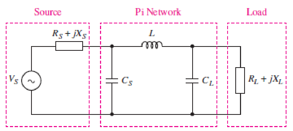
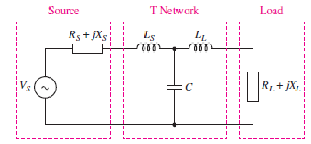
You would like to maximize power transfer to a 50 Ω antenna for VHF communications at 100 MHz. The source has an impedance of 10 + j5 Ω at this frequency. Design a T or Pi matching network for maximum power transfer (see Figs. 11.51 and 11.52). Simulate your design using SPICE, and use an appropriate supporting argument to verify maximum power transfer.
■ FIGURE 11.51
■ FIGURE 11.52
Expert Solution & Answer
Want to see the full answer?
Check out a sample textbook solution
Students have asked these similar questions
3-3) Similar to Lathi & Ding prob. 3.3-7.
The signals in the figure below are modulated signals with carrier cos(5t). Find the Fourier transforms of
these signals using the appropriate properties of the Fourier transform and text Table 3.1. The sketch the
magnitude and phase spectra for figure parts (a) and (b).
Hint: these functions can be expressed in the form g(t) cos(2лfot)
(a)
1
1
2π
www.
σπ
(b)
(c)
όπ
3-1) Similar to Lathi & Ding prob. 3.1-1. Use direct integration to find the Fourier transforms of the
signals shown below.
a) g₁(t) = II(t − 2) + 2 exp (−3|t|)
b) g(t) = d(t+2)+3e¯u (t − 2)
3-2)
Lathi & Ding prob. 3.1-5. From the definition in eq. 3.1b, find the inverse Fourier transforms of the
spectra in the figure below.
G(f)
COS лf
10
(a)
G(f) 1
-B
B
(b)
Chapter 11 Solutions
ENGINEERING CIRCUIT...(LL)>CUSTOM PKG.<
Ch. 11.1 - A current source of 12 cos 2000t A, a 200 ....Ch. 11.2 - Given the phasor voltage across an impedance ,...Ch. 11.2 - Prob. 3PCh. 11.2 - Prob. 4PCh. 11.2 - A voltage source vs is connected across a 4...Ch. 11.3 - If the 30 mH inductor of Example 11.7 is replaced...Ch. 11.4 - Calculate the effective value of each of the...Ch. 11.5 - For the circuit of Fig. 11.16, determine the power...Ch. 11.6 - Prob. 10PCh. 11 - Prob. 1E
Ch. 11 - Determine the power absorbed at t = 1.5 ms by each...Ch. 11 - Calculate the power absorbed at t = 0, t = 0+, and...Ch. 11 - Three elements are connected in parallel: a 1 k...Ch. 11 - Let is = 4u(t) A in the circuit of Fig. 11.28. (a)...Ch. 11 - Prob. 6ECh. 11 - Assuming no transients are present, calculate the...Ch. 11 - Prob. 8ECh. 11 - Prob. 9ECh. 11 - Prob. 10ECh. 11 - The phasor current I=915mA (corresponding to a...Ch. 11 - A phasor voltage V=10045V (the sinusoid operates...Ch. 11 - Prob. 13ECh. 11 - Prob. 14ECh. 11 - Find the average power for each element in the...Ch. 11 - (a) Calculate the average power absorbed by each...Ch. 11 - Prob. 17ECh. 11 - Prob. 18ECh. 11 - Prob. 19ECh. 11 - The circuit in Fig. 11.36 has a series resistance...Ch. 11 - Prob. 21ECh. 11 - Prob. 22ECh. 11 - Prob. 23ECh. 11 - Prob. 24ECh. 11 - Prob. 25ECh. 11 - Prob. 26ECh. 11 - Prob. 27ECh. 11 - Prob. 28ECh. 11 - Prob. 29ECh. 11 - Prob. 30ECh. 11 - Prob. 31ECh. 11 - Prob. 32ECh. 11 - Prob. 33ECh. 11 - (a) Calculate both the average and rms values of...Ch. 11 - Prob. 35ECh. 11 - FIGURE 11.43 Calculate the power factor of the...Ch. 11 - Prob. 37ECh. 11 - Prob. 38ECh. 11 - Prob. 40ECh. 11 - Prob. 41ECh. 11 - Prob. 42ECh. 11 - Prob. 43ECh. 11 - Compute the complex power S (in polar form) drawn...Ch. 11 - Calculate the apparent power, power factor, and...Ch. 11 - Prob. 46ECh. 11 - Prob. 48ECh. 11 - Prob. 49ECh. 11 - Prob. 50ECh. 11 - Prob. 51ECh. 11 - Prob. 52ECh. 11 - FIGURE 11.49 Instead of including a capacitor as...Ch. 11 - Prob. 54ECh. 11 - A load is drawing 10 A rms when connected to a...Ch. 11 - For the circuit of Fig. 11.50, assume the source...Ch. 11 - Prob. 57ECh. 11 - A source 45 sin 32t V is connected in series with...Ch. 11 - Prob. 60ECh. 11 - FIGURE 11.51 The circuit in Fig. 11.51 uses a Pi...Ch. 11 - Prob. 62ECh. 11 - Prob. 63ECh. 11 - You would like to maximize power transfer to a 50 ...
Knowledge Booster


Learn more about
Need a deep-dive on the concept behind this application? Look no further. Learn more about this topic, electrical-engineering and related others by exploring similar questions and additional content below.Similar questions
- Construct a battery pack to deliver 360V and 450-mile range for a vehicle that consumes 200 Wh/mile, from prismatic cells with 25Ah and 3.6 V. Physical dimensions of the cell are 0.5 cm thickness, 20 cm width and 40 cm length. a) Report configuration of the battery pack. 10-points b) Resistance of each cell is 0.05 Ohm, calculate the total internal resistance of the battery pack. 10-points c) Calculate the voltage drop during discharge when the battery is discharged at 100A. 10-points d) Calculate the amount of anode and cathode to build a prismatic cell with 25Ah capacity. Assume the cell chemistry as: Si anode and [Li(Ni1/3Co1/3Mn1/3)O2] cathode. Atomic weight of elements: Li=7, Si = 28, Ni=58, Co=59, Mn=55, O=16, 10-points e) Calculate the theoretical specific energy (Wh/kg) and practical energy density (Wh/liter) of the battery pack. 10-points f) Calculate the thickness on anode and cathode coating assuming each electrode has 30%…arrow_forwardI need help with this problem and an explanation of the solution for the image described below. (Introduction to Signals and Systems)arrow_forwardDesign a battery pack for an electric bike that consumes in average 10Wh/mile and drive 30 miles per charge. The battery state of charge window is 80%. Design the battery by using new commercial cylindrical cells with 20mm diameter and 80mm height. The battery is constructed based on graphite anode C6 and cathode Li(Ni0.8Co0.15Al0,05)O2 that provides 3.75V at the cell level and 10Ah capacity. Density of anode is 2.2 g/cm3 and density of cathode is 4.5 g/cm3. Report on the battery pack configuration if the required battery pack voltage is 75 volts. If the thickness of anode and cathode is limited to 130 microns (130 x 10-4 cm) calculate the total electrode surface area in each cell. Assume the porosity of electrodes are 30%. Calculate the weight of active materials (anode and cathode) in grams and the total current collector’s and electrolyte membrane areas in (cm2).arrow_forward
- DO NOT USE AI NEED HANDWRITTEN SOLUTION Find total impedance of circuit in polar form and power factor.arrow_forwardDo NOT WANT AI. need diagram fully labeled pleasearrow_forwardCalculate the current magnitude in the coils e1, e2 of theMagnetic circuit, if:ɸa = 3.00 x 10^-3 Wb, φb = 0.80 x 10^-3 Wb, ɸc = 2.20 x 10^-3 Wb L ab = 0.10 m,A ab = 5.0 cm^2L afeb = L acdb = 0.40 mA afeb = A acdb = 20 cm^2 MATERIAL CHARACTERISTICSH (At/m) 240 350 530 1300 5000 9000B (T) 0.7 0.9 1.1 1.3 1.5 1.6arrow_forward
arrow_back_ios
SEE MORE QUESTIONS
arrow_forward_ios
Recommended textbooks for you
 Power System Analysis and Design (MindTap Course ...Electrical EngineeringISBN:9781305632134Author:J. Duncan Glover, Thomas Overbye, Mulukutla S. SarmaPublisher:Cengage Learning
Power System Analysis and Design (MindTap Course ...
Electrical Engineering
ISBN:9781305632134
Author:J. Duncan Glover, Thomas Overbye, Mulukutla S. Sarma
Publisher:Cengage Learning
Types of Energy for Kids - Renewable and Non-Renewable Energies; Author: Smile and Learn - English;https://www.youtube.com/watch?v=w16-Uems2Qo;License: Standard Youtube License