ENGINEERING CIRCUIT...(LL)>CUSTOM PKG.<
9th Edition
ISBN: 9781260540666
Author: Hayt
Publisher: MCG CUSTOM
bartleby

Videos

Textbook Question
Book Icon
Chapter 11, Problem 53E

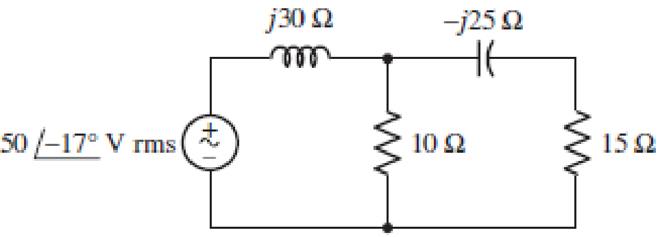
Chapter 11, Problem 53E, FIGURE 11.49 Instead of including a capacitor as indicated in Fig. 11.49, the circuit is erroneously

■ FIGURE 11.49

Instead of including a capacitor as indicated in Fig. 11.49, the circuit is erroneously constructed using two identical inductors, each having an impedance of j30 W at the operating frequency of 50 Hz. (a) Compute the complex power delivered to each passive component. (b) Verify your solution by calculating the complex power supplied by the source. (c) At what power factor is the source operating?

(a)

Expert Solution
Check Mark
To determine

Find the complex power delivered to each passive element when j25Ω capacitor is replace with j30Ω inductor in the circuit in Figure 11.49 in the textbook.

Answer to Problem 53E

The complex power delivered to j30Ω inductive reactance of the left-loop inductor, 10Ω resistor, j30Ω inductive reactance of the right-loop inductor and 15Ω resistor are 68.790°VA_, 16.890°VA_, 4.5090°VA_, and 2.260°VA_, respectively.

Explanation of Solution

Given data:

Refer to Figure 11.49 in the textbook for the given circuit.

Vs=5017°Vrms

j25Ω capacitor is replace with j30Ω inductor in the given circuit.

Operating frequency is 50 Hz.

Formula used:

Write the expression for complex power delivered to the element as follows:

S=VI*        (1)

Here,

V is the voltage across the element and

I is the current through the element.

Write the expression for current in terms of voltage and impedance as follows:

I=VZ        (2)

Calculation:

Consider j25Ω capacitor is replace with j30Ω inductor in the given circuit and find the equivalent impedance for the circuit to the right of j30Ω inductive reactance of the inductor as follows:

Zeq=[(15+j30)(10)(15+j30)+(10)]Ω=(8.3606+j1.9672)Ω=8.588913.24°Ω

Use the expression in Equation (2) and find the source current as follows:

Is=Vsj30Ω+Zeq

Substitute 5017°V for Vs and (8.3606+j1.9672)Ω for Zeq to obtain the source current as follows:

Is=5017°Vj30Ω+(8.3606+j1.9672)Ω=5017°V(8.3606+j31.9672)Ω=5017°33.042475.34°A=1.513292.34°A

Use voltage division rule and find the voltage across j30Ω left-loop inductor as follows:

Vj30Ωleft=(j30Ωj30Ω+Zeq)Vs

Substitute 5017°V for Vs and  (8.3606+j1.9672)Ω for Zeq to obtain the value of Vj30Ω.

Vj30Ωleft=[j30Ωj30Ω+ (8.3606+j1.9672)Ω](5017°V)=[3090°33.042475.34°](5017°V)=45.39622.34°V

Modify the expression in Equation (1) for the complex power delivered to j30Ω inductive reactance of the left-loop inductor as follows:

Sj30Ωleft=Vj30Ωleft(Is)*

Substitute 45.39622.34°V for Vj30Ωleft and 1.513292.34°A for Is to obtain the complex power delivered to j30Ω inductive reactance of the inductor.

Sj30Ωleft=(45.39622.34°V)(1.513292.34°A)*=(45.39622.34°V)(1.513292.34°A)=68.693590°VA68.790°VA

Consider the node voltage across the shunt branches as V1 and find the value of V1 by voltage division rule as follows:

V1=(Zeqj30Ω+Zeq)Vs

Substitute 5017°V for Vs and  (8.3606+j1.9672)Ω for Zeq to obtain the value of V1.

V1=[ (8.3606+j1.9672)Ωj30Ω+ (8.3606+j1.9672)Ω](5017°V)=[8.588513.24°Ω33.042475.34°](5017°V)=12.996179.1°V

Use current division rule and find the current through 10Ω resistor as follows:

I10Ω=[(15+j30)Ω10Ω+(15+j30)Ω]Is

Substitute 1.513292.34°A for Is to obtain the value of current through 10Ω resistor.

I10Ω=[(15+j30)Ω10Ω+(15+j30)Ω](1.513292.34°A)=(33.541063.43°Ω39.051250.19°Ω)(1.513292.34°A)=1.299679.1°A

Modify the expression in Equation (1) for the complex power delivered to the 10Ω resistor as follows:

S10Ω=V1(I10Ω)*

Substitute 12.996179.1°V for V1 and 1.299679.1°A for I10Ω to obtain the complex power delivered to the 10Ω resistor.

S10Ω=(12.996179.1°V)(1.299679.1°A)*=(12.996179.1°V)(1.299679.1°A)=16.88960°VA=16.890°VA

Use voltage division rule and find the voltage across j30Ω right-loop inductor as follows:

Vj30Ωright=(j30Ω15Ω+j30Ω)V1

Substitute 12.996179.1°V for V1 to obtain the voltage across j30Ω right-loop inductor.

Vj30Ωright=(j30Ω15Ω+j30Ω)(12.996179.1°V)=(3090°Ω33.541063.43°Ω)(12.996179.1°V)=11.624052.53°V

Use current division rule and find the current through (15+j30)Ω branch as follows:

I(15+j30)Ω=[10Ω10Ω+(15+j30)Ω]Is

Substitute 1.513292.34°A for Is to obtain the value of current through (15+j30)Ω branch.

I(15+j30)Ω=[10Ω10Ω+(15+j30)Ω](1.513292.34°A)=(100°Ω39.051250.19°Ω)(1.513292.34°A)=0.3875142.53°A

Modify the expression in Equation (1) for the complex power delivered to the j30Ω right-loop inductor as follows:

Sj30Ωright=Vj30Ωright(I(15+j30)Ω)*

Substitute 11.624052.53°V for Vj30Ωright and 0.3875142.53°A for I(15+j30)Ω to obtain the complex power delivered to the j30Ω right-loop inductor.

Sj30Ωright=(11.624052.53°V)(0.3875142.53°A)*=(11.624052.53°V)(0.3875142.53°A)=4.504390°VA4.5090°VA

Use voltage division rule and find the voltage across 15Ω resistor as follows:

V15Ω=(15Ω15Ω+j30Ω)V1

Substitute 12.996179.1°V for V1 to obtain the voltage across 15Ω resistor.

V15Ω=(15Ω15Ω+j30Ω)(12.996179.1°V)=(15Ω33.541063.43°Ω)(12.996179.1°V)=5.8120142.53°V

Modify the expression in Equation (1) for the complex power delivered to the 15Ω resistor as follows:

S15Ω=V15Ω(I(15+j30)Ω)*

Substitute 5.8120142.53°V for V15Ω and 0.3875142.53°A for I(15+j30)Ω to obtain the complex power delivered to the 15Ω resistor.

S15Ω=(5.8120142.53°V)(0.3875142.53°A)*=(5.8120142.53°V)(0.3875142.53°A)=2.25210°VA2.260°VA

Conclusion:

Thus, the complex power delivered to j30Ω inductive reactance of the left-loop inductor, 10Ω resistor, j30Ω inductive reactance of the right-loop inductor and 15Ω resistor are 68.790°VA_, 16.890°VA_, 4.5090°VA_, and 2.260°VA_, respectively.

(b)

Expert Solution
Check Mark
To determine

Verify the solution obtained in Part (a) by calculating the complex power supplied by the source.

Explanation of Solution

Calculation:

Modify the expression in Equation (1) for the complex power supplied by the source as follows:

Ss=Vs(Is)*

Substitute 5017°V for Vs and 1.513292.34°A for Is to obtain the complex power supplied by the source.

Ss=(5017°V)(1.513292.34°A)*=(5017°V)(1.513292.34°A)=75.6675.34°VA

Write the expression for sum of complex delivered to (or absorbed by) each passive element as follows:

Sabs=Sj30Ωleft+S10Ω+Sj30Ωright+S15Ω

From Part (a), substitute 68.790°VA for Sj30Ωleft, 16.890°VA for S10Ω, 4.5090°VA for Sj30Ωright, and 2.260°VA for S15Ω to obtain the complex power absorbed by each passive element.

Sabs=68.790°VA+16.890°VA+4.5090°VA+2.260°VA=[(0+j68.7)+(16.89+0j)+(0+j4.50)+(2.26+0j)]VA=(19.15+j73.2)VA=75.6675.34°VA

From the calculation, it is clear that, the complex power supplied by the source is equal to the complex power delivered to each passive element.

Conclusion:

Thus, the solution obtained in Part (a) is verified.

(c)

Expert Solution
Check Mark
To determine

Find the power factor of the source.

Answer to Problem 53E

The power factor of the source is 0.253 lagging.

Explanation of Solution

Formula used:

Write the expression for complex power in the rectangular form as follows:

S=P+jQ        (3)

Here,

P is the average power and

Q is the reactive power.

Write the expression for power factor as follows:

PF=cos[tan1(QP)]        (4)

Calculation:

Rewrite the expression for complex power supplied by the source in rectangular form as follows:

Ss=(19.1482+j73.1968)VA

Compare the complex power supplied by the source with the expression in Equation (3) and write the average and reactive power supplied by the source as follows:

P=19.1482WQ=73.1968VAR

Substitute 19.1482 W for P and 73.1968 VAR for Q in Equation (4) to obtain the value of source power factor.

PF=cos[tan1(73.1968VAR19.1482W)]=cos(75.34°)=0.2530

If the imaginary part of the complex power (reactive power) is positive value, then the load has lagging power factor. If the imaginary part is negative value, then the load has leading power factor.

As the imaginary part of the given complex power is positive value, the power factor is lagging power factor.

PF=0.253lagging

Conclusion:

Thus, the power factor of the source is 0.253 lagging.

Want to see more full solutions like this?

Subscribe now to access step-by-step solutions to millions of textbook problems written by subject matter experts!
Students have asked these similar questions
7.2 At t = 0, the switch in the circuit shown moves instantaneously from position a to position b. a) Calculate v, for t≥ 0. b) What percentage of the initial energy stored in the inductor is eventually dissipated in the 4 resistor? 6Ω a w + 10 0.32 H3 403 6.4 A =0 b Answer: (a) -8e-10 V, t = 0; (b) 80%.
At t = 0, the switch closes. Find the IL(t) and VL(t) for t≥ 0 in t and s domain. Can you help me? 1) (+. 24V ง Anahtar t=0 anında kapatılıyor. to icin TL(t) ve bulunuz. J 3√√√2 ww مفروم + t=0 $6.5 5H VLCH) 2.2 Vilt)
"For the network in the figure, determine RE and RB if A₁ Zb = BRE." = -10 and re = 3.8. Assume that

Chapter 11 Solutions

ENGINEERING CIRCUIT...(LL)>CUSTOM PKG.<

Ch. 11 - Determine the power absorbed at t = 1.5 ms by each...Ch. 11 - Calculate the power absorbed at t = 0, t = 0+, and...Ch. 11 - Three elements are connected in parallel: a 1 k...Ch. 11 - Let is = 4u(t) A in the circuit of Fig. 11.28. (a)...Ch. 11 - Prob. 6ECh. 11 - Assuming no transients are present, calculate the...Ch. 11 - Prob. 8ECh. 11 - Prob. 9ECh. 11 - Prob. 10ECh. 11 - The phasor current I=915mA (corresponding to a...Ch. 11 - A phasor voltage V=10045V (the sinusoid operates...Ch. 11 - Prob. 13ECh. 11 - Prob. 14ECh. 11 - Find the average power for each element in the...Ch. 11 - (a) Calculate the average power absorbed by each...Ch. 11 - Prob. 17ECh. 11 - Prob. 18ECh. 11 - Prob. 19ECh. 11 - The circuit in Fig. 11.36 has a series resistance...Ch. 11 - Prob. 21ECh. 11 - Prob. 22ECh. 11 - Prob. 23ECh. 11 - Prob. 24ECh. 11 - Prob. 25ECh. 11 - Prob. 26ECh. 11 - Prob. 27ECh. 11 - Prob. 28ECh. 11 - Prob. 29ECh. 11 - Prob. 30ECh. 11 - Prob. 31ECh. 11 - Prob. 32ECh. 11 - Prob. 33ECh. 11 - (a) Calculate both the average and rms values of...Ch. 11 - Prob. 35ECh. 11 - FIGURE 11.43 Calculate the power factor of the...Ch. 11 - Prob. 37ECh. 11 - Prob. 38ECh. 11 - Prob. 40ECh. 11 - Prob. 41ECh. 11 - Prob. 42ECh. 11 - Prob. 43ECh. 11 - Compute the complex power S (in polar form) drawn...Ch. 11 - Calculate the apparent power, power factor, and...Ch. 11 - Prob. 46ECh. 11 - Prob. 48ECh. 11 - Prob. 49ECh. 11 - Prob. 50ECh. 11 - Prob. 51ECh. 11 - Prob. 52ECh. 11 - FIGURE 11.49 Instead of including a capacitor as...Ch. 11 - Prob. 54ECh. 11 - A load is drawing 10 A rms when connected to a...Ch. 11 - For the circuit of Fig. 11.50, assume the source...Ch. 11 - Prob. 57ECh. 11 - A source 45 sin 32t V is connected in series with...Ch. 11 - Prob. 60ECh. 11 - FIGURE 11.51 The circuit in Fig. 11.51 uses a Pi...Ch. 11 - Prob. 62ECh. 11 - Prob. 63ECh. 11 - You would like to maximize power transfer to a 50 ...
Knowledge Booster
Background pattern image
Electrical Engineering
Learn more about
Need a deep-dive on the concept behind this application? Look no further. Learn more about this topic, electrical-engineering and related others by exploring similar questions and additional content below.
Similar questions
SEE MORE QUESTIONS
Recommended textbooks for you
Text book image
Electric Motor Control
Electrical Engineering
ISBN:9781133702818
Author:Herman
Publisher:CENGAGE L
02 - Sinusoidal AC Voltage Sources in Circuits, Part 1; Author: Math and Science;https://www.youtube.com/watch?v=8zMiIHVMfaw;License: Standard Youtube License