
Videos
Problems 11–2 and 11–3 raise the question of the reliability of the bearing pair on the shaft. Since the combined reliabilities R is R1R2, what is the reliability of the two bearings (probability that either or both will not fail) as a result of your decisions in Probs. 11–2 and 11–3? What does this mean in setting reliability goals for each of the bearings of the pair on the shaft?
The reliability of two bearing.
Answer to Problem 4P
The reliability of two bearing is
Setting the reliability goals for each bearing depends on the combined reliability of the bearings.
Explanation of Solution
Write the expression for multiple of rating life for bearing.
Here, multiple of rating life for design is
Write the regression equation for bearing load life.
Here, the bearing load for design is
Write the equation for bearing life.
Here, the rating life in hour is
The below figure shows the relationship between bearing load and dimensionless life in terms of logarithmic values.
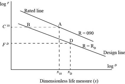
Figure-(1)
Write the equation for reliability along a constant load line
Here, the characteristic parameter is
Write the expression for catalog rating in terms of application factor.
Here, catalog rating is
Write the expression for combined reliabilities.
Here, combined reliability is
Conclusion:
For first bearing.
Substitute
Substitute
Thus, the multiple of rating life of bearing is
Substitute
For ball bearing, the value of constant
Substitute
Substitute
Refer table 11-2 “Dimensions and Load Rating of Ball Bearing” to obtain the ball bearing at catalog rating of
Thus, the catalog rating of bearing is
Substitute
Substitute
Substitute
Thus, the reliability of the bearing is
For second bearing:
Substitute
Thus, the multiple of rating life of the bearing is
Substitute
Substitute
For roller bearing, the value of constant
Substitute
Substitute
Refer to table 11-2 “Dimensions and Load Rating of Ball Bearing” to obtain the ball bearing at catalog rating of
Thus, the catalog rating of the bearing is
Substitute
Substitute
Substitute
Thus, the reliability of the bearing is
Substitute
Reliability goal can be achieved by setting the reliability of one bearing and according to it the reliability of other bearing is achieved.
Substitute
Thus, the setting the reliability goals for each bearing depends on the combined reliability.
Want to see more full solutions like this?
Chapter 11 Solutions
Shigley's Mechanical Engineering Design (McGraw-Hill Series in Mechanical Engineering)


- 12. Compute the estimated actual endurance limit for SAE 4130 WQT 1300 steel bar with a rectangular cross sec- tion of 20.0 mm by 60 mm. It is to be machined and subjected to repeated and reversed bending stress. A reli- ability of 99% is desired.arrow_forward28. The shaft shown in Figure P5-28 is supported by bear- ings at each end, which have bores of 20.0 mm. Design the shaft to carry the given load if it is steady and the shaft is stationary. Make the dimension a as large as pos- sible while keeping the stress safe. Determine the required d = 20mm D = ? R = ?| 5.4 kN d=20mm Length not to scale -a = ?- +а= a = ? + -125 mm- -250 mm- FIGURE P5-28 (Problems 28, 29, and 30)arrow_forward2. A strut in a space frame has a rectangular cross section of 10.0 mm by 30.0 mm. It sees a load that varies from a tensile force of 20.0 kN to a compressive force of 8.0 kN.arrow_forward
- find stress at Qarrow_forwardI had a theoretical question about attitude determination. In the attached images, I gave two axis and angles. The coefficient of the axes are the same and the angles are the same. The only difference is the vector basis. Lets say there is a rotation going from n hat to b hat. Then, you introduce a intermediate rotation s hat. So, I want to know if the DCM produced from both axis and angles will be the same or not. Does the vector basis affect the numerical value of the DCM? The DCM formula only cares about the coefficient of the axis and the angle. So, they should be the same right?arrow_forward3-15. A small fixed tube is shaped in the form of a vertical helix of radius a and helix angle y, that is, the tube always makes an angle y with the horizontal. A particle of mass m slides down the tube under the action of gravity. If there is a coefficient of friction μ between the tube and the particle, what is the steady-state speed of the particle? Let y γ 30° and assume that µ < 1/√3.arrow_forward
- The plate is moving at 0.6 mm/s when the force applied to the plate is 4mN. If the surface area of the plate in contact with the liquid is 0.5 m^2, deterimine the approximate viscosity of the liquid, assuming that the velocity distribution is linear.arrow_forward3-9. Given that the force acting on a particle has the following components: Fx = −x + y, Fy = x − y + y², F₂ = 0. Solve for the potential energy V. -arrow_forward2.5 (B). A steel rod of cross-sectional area 600 mm² and a coaxial copper tube of cross-sectional area 1000 mm² are firmly attached at their ends to form a compound bar. Determine the stress in the steel and in the copper when the temperature of the bar is raised by 80°C and an axial tensile force of 60 kN is applied. For steel, E = 200 GN/m² with x = 11 x 10-6 per °C. E = 100 GN/m² with α = 16.5 × 10⁻⁶ For copper, per °C. [E.I.E.] [94.6, 3.3 MN/m².]arrow_forward
- 3–16. A particle of mass m is embedded at a distance R from the center of a massless circular disk of radius R which can roll without slipping on the inside surface of a fixed circular cylinder of radius 3R. The disk is released with zero velocity from the position shown and rolls because of gravity, all motion taking place in the same vertical plane. Find: (a) the maximum velocity of the particle during the resulting motion; (b) the reaction force acting on the disk at the point of contact when it is at its lowest position. KAR 60° 3R M Fig. P3-16arrow_forwardI have figured out the support reactions, Ay = 240 kN, Ax = 0 kN, Ma = 639.2 kN*m and the constant term for V(x) is 240. I am not figuring out the function of x part right. Show how to derive V(x) and M(x) for this distributed load.arrow_forward2.4 (A). A 75 mm diameter compound bar is constructed by shrinking a circular brass bush onto the outside of a 50 mm diameter solid steel rod. If the compound bar is then subjected to an axial compressive load of 160 kN determine the load carried by the steel rod and the brass bush and the compressive stress set up in each material. For steel, E 210 GN/m²; for brass, E = 100 GN/m². [I. Struct. E.] [100.3, 59.7 kN; 51.1, 24.3 MN/m².]arrow_forward
 Elements Of ElectromagneticsMechanical EngineeringISBN:9780190698614Author:Sadiku, Matthew N. O.Publisher:Oxford University Press
 Mechanics of Materials (10th Edition)Mechanical EngineeringISBN:9780134319650Author:Russell C. HibbelerPublisher:PEARSON
 Thermodynamics: An Engineering ApproachMechanical EngineeringISBN:9781259822674Author:Yunus A. Cengel Dr., Michael A. BolesPublisher:McGraw-Hill Education
 Control Systems EngineeringMechanical EngineeringISBN:9781118170519Author:Norman S. NisePublisher:WILEY
 Mechanics of Materials (MindTap Course List)Mechanical EngineeringISBN:9781337093347Author:Barry J. Goodno, James M. GerePublisher:Cengage Learning
 Engineering Mechanics: StaticsMechanical EngineeringISBN:9781118807330Author:James L. Meriam, L. G. Kraige, J. N. BoltonPublisher:WILEY