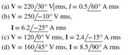
For the following voltage and current phasors, calculate the complex power, apparent power, real power, and reactive power. Specify whether the pf is leading or lagging.
For the following voltage and current phasors, calculate the complex power, apparent power, real power, and reactive power. Specify whether the pf is leading or lagging.
For the following voltage and current phasors, calculate the complex power, apparent power, real power, and reactive power. Specify whether the pf is leading or lagging.
(a)
Expert Solution
To determine
Find the complex power, apparent power, real power, and reactive power for the given voltage and current phasor. Also mention whether the power factor is leading or lagging.
Answer to Problem 46P
The complex power is S=(95.26−j55)VA, apparent power is S=110VA, real power is P=95.26W, reactive power is Q=−55VAR, and the power factor pf is leading for the given voltage and current phasor.
Explanation of Solution
Given data:
The voltage phasor,
Vrms=220∠30°V (1)
The current phasor,
Irms=0.5∠60°A (2)
Formula used:
Write the expression to find the complex power S.
S=Vrms(Irms)* (3)
Here,
Vrms is the root mean square value of voltage, and
Irms is the root mean square value of current.
Write the expression for complex power S.
S=P+jQ (4)
Here,
P is the real power, and
Q is the reactive power.
Calculation:
Substitute 220∠30°V for Vrms and 0.5∠60°A for Irms in equation (3) to find the complex power S in VA.
S=220∠30°V(0.5∠60°A)*=(220∠30°V)(0.5∠−60°A)
S=110∠−30°VA (5)
Convert equation (5) from polar form to rectangular form. Therefore,
S=(95.26−j55)VA (6)
From equation (5), the apparent power S=|S|=110VA.
On comparing equation (4) and (6), the real power P is 95.26W and the reactive power Q is −55VAR.
From equation (1) and (2), the power factor pf is leading because the current leads the voltage, which implies a capacitive load.
Conclusion:
Thus, the complex power is S=(95.26−j55)VA, apparent power is S=110VA, real power is P=95.26W, reactive power is Q=−55VAR, and the power factor pf is leading for the given voltage and current phasor.
(b)
Expert Solution
To determine
Find the complex power, apparent power, real power, and reactive power for the given voltage and current phasor. Also mention whether the power factor is leading or lagging.
Answer to Problem 46P
The complex power is S=(1497.2−j401.2)VA, apparent power is S=1550VA, real power is P=1497.2W, reactive power is Q=401.2VAR, and the power factor pf is lagging for the given voltage and current phasor.
Explanation of Solution
Given data:
The voltage phasor,
Vrms=250∠−10°V (7)
The current phasor,
Irms=6.2∠−25°A (8)
Calculation:
Substitute 250∠−10°V for Vrms and 6.2∠−25°A for Irms in equation (3) to find the complex power S in VA.
S=250∠−10°V(6.2∠−25°A)*=(250∠−10°V)(6.2∠25°A)
S=1550∠15°VA (9)
Convert equation (9) from polar form to rectangular form. Therefore,
S=(1497.2+j401.2)VA (10)
From equation (9), the apparent power S=|S|=1550VA.
On comparing equation (4) and (10), the real power P is 1497.2W and the reactive power Q is 401.2VAR.
From equation (7) and (8), the power factor pf is lagging because the current lags the voltage, which implies an inductive load.
Conclusion:
Thus, the complex power is S=(1497.2−j401.2)VA, apparent power is S=1550VA, real power is P=1497.2W, reactive power is Q=401.2VAR, and the power factor pf is lagging for the given voltage and current phasor.
(c)
Expert Solution
To determine
Find the complex power, apparent power, real power, and reactive power for the given voltage and current phasor. Also mention whether the power factor is leading or lagging.
Answer to Problem 46P
The complex power is S=(278.2+j74.54)VA, apparent power is S=288VA, real power is P=278.2W, reactive power is Q=74.54VAR, and the power factor pf is lagging for the given voltage and current phasors.
Explanation of Solution
Given data:
The voltage phasor,
Vrms=120∠0°V (11)
The current phasor,
Irms=2.4∠−15°A (12)
Calculation:
Substitute 120∠0°V for Vrms and 2.4∠−15°A for Irms in equation (3) to find the complex power S in VA.
S=120∠0°V(2.4∠−15°A)*=(120∠0°V)(2.4∠15°A)
S=288∠15° (13)
Convert equation (13) from polar form to rectangular form. Therefore,
S=(278.2+j74.54)VA (14)
From equation (13), the apparent power S=|S|=288VA.
On comparing equation (4) and (14), the real power P is 278.2W and the reactive power Q is 74.54VAR.
From equation (11) and (12), the power factor pf is lagging because the current lags the voltage, which implies an inductive load.
Conclusion:
Thus, the complex power is S=(278.2+j74.54)VA, apparent power is S=288VA, real power is P=278.2W, reactive power is Q=74.54VAR, and the power factor pf is lagging for the given voltage and current phasor.
(d)
Expert Solution
To determine
Find the complex power, apparent power, real power, and reactive power for the given voltage and current phasor. Also mention whether the power factor is leading or lagging.
Answer to Problem 46P
The complex power is S=(961.7−j961.7)VA, apparent power is S=1360VA, real power is P=961.7W, reactive power is Q=−961.7VAR, and the power factor pf is leading for the given voltage and current phasors.
Explanation of Solution
Given data:
The voltage phasor,
Vrms=160∠45°V (15)
The current phasor,
Irms=8.5∠90°A (16)
Calculation:
Substitute 160∠45°V for Vrms and 8.5∠90°A for Irms in equation (3) to find the complex power S in VA.
S=160∠45°V(8.5∠90°A)*=(160∠45°V)(8.5∠−90°A)
S=1360∠−45° (17)
Convert equation (17) from polar form to rectangular form. Therefore,
S=(961.7−j961.7)VA (18)
From equation (17), the apparent power S=|S|=1360VA.
On comparing equation (4) and (18), the real power P is 961.7W and the reactive power Q is −961.7VAR.
From equation (15) and (16), the power factor pf is leading because the current leads the voltage, which implies a capacitive load.
Conclusion:
Thus, the complex power is S=(961.7−j961.7)VA, apparent power is S=1360VA, real power is P=961.7W, reactive power is Q=−961.7VAR, and the power factor pf is leading for the given voltage and current phasor.
Want to see more full solutions like this?
Subscribe now to access step-by-step solutions to millions of textbook problems written by subject matter experts!
Need a deep-dive on the concept behind this application? Look no further. Learn more about this topic, electrical-engineering and related others by exploring similar questions and additional content below.
NMOS vs PMOS and Enhancement vs Depletion Mode MOSFETs | Intermediate Electronics; Author: CircuitBread;https://www.youtube.com/watch?v=kY-ka0PriaE;License: Standard Youtube License


 Power System Analysis and Design (MindTap Course ...Electrical EngineeringISBN:9781305632134Author:J. Duncan Glover, Thomas Overbye, Mulukutla S. SarmaPublisher:Cengage Learning