
Videos
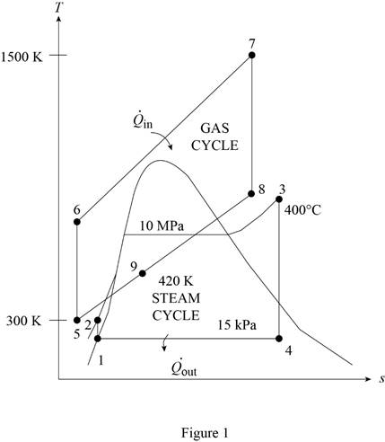
The gas-turbine portion of a combined gas–steam power plant has a pressure ratio of 16. Air enters the compressor at 300 K at a rate of 14 kg/s and is heated to 1500 K in the combustion chamber. The combustion gases leaving the gas turbine are used to heat the steam to 400°C at 10 MPa in a heat exchanger. The combustion gases leave the heat exchanger at 420 K. The steam leaving the turbine is condensed at 15 kPa. Assuming all the compression and expansion processes to be isentropic, determine (a) the mass flow rate of the steam, (b) the net power output, and (c) the thermal efficiency of the combined cycle. For air, assume constant specific heats at room temperature.
(a)
The mass flow rate of the steam.
Answer to Problem 82P
The mass flow rate of the steam is
Explanation of Solution
Show the
Determine the temperature of gas cycle at state 6.
Here, the temperature of gas cycle at state 5 is
Determine the rate of heat transfer into the gas turbine.
Here, the mass flow rate of air is
Determine the power rate for compressor of gas turbine.
Determine the temperature of gas cycle at state 8.
Here, the pressure of gas cycle at state 8 is
Determine the power rate for gas turbine of gas turbine.
Determine the net power output of the gas cycle.
Determine input work done per unit mass of the isentropic process for the steam cycle.
Here, the specific volume of the steam is
Determine the specific enthalpy at state 2 of the steam cycle.
Here, the specific enthalpy at the state 1 of the steam cycle is
Determine the quality at state 4 of the stream cycle.
Here, the specific entropy at state 4 is
Determine the specific enthalpy at state 4 of the steam cycle.
Here, the specific enthalpy of saturated liquid is
Write the expression for the steady-flow energy balance equation.
Here, the total energy rate of entering the system is
Substitute
Here, the temperature of gas cycle at state 8 is
Determine the power rate for gas turbine of steam cycle.
Here, the mass flow rate of the steam is
Determine the power rate of the isentropic process for the steam cycle.
Here, the mass flow rate of the steam is
Determine the net power output of the steam cycle.
Conclusion:
From the Table A-2, “Ideal-gas specific heats of various common gases”, obtain the value of specific heat of constant pressure and the ratio of specific heat at temperature of
Substitute 300 K for
Substitute
Substitute
Substitute 1500 K for
Substitute
Substitute 11547 kW for
From the Table A-4, “Saturated water-Pressure table”, obtain the value of the initial specific enthalpy at liquid state, specific volume at the liquid state, the specific entropy at liquid state, the specific enthalpy change upon vaporization at pressure, and the specific entropy change upon vaporization at pressure of 15 kPa as:
Substitute
Substitute
From the Table A-6, “Superheated water”, obtain the value of the specific enthalpy at state 3 and the specific entropy at state 3 at pressure of 10 MPa and temperature of
Substitute
Substitute 0.7528 for
Substitute
Thus, the mass flow rate of the steam is
Substitute
Substitute
Substitute 1384.013 kW for
(b)
The net work output of the combined cycle.
Answer to Problem 82P
The net work output of the combined cycle is
Explanation of Solution
Determine the net power output of combined cycle.
Conclusion:
Substitute 1371 kW for
Thus, the net work output of the combined cycle is
(c)
The thermal efficiency of the combined cycle.
Answer to Problem 82P
The thermal efficiency of the combined cycle is
Explanation of Solution
Determine the thermal efficiency of the combined cycle.
Conclusion:
Substitute 7819 kW for
Thus, the thermal efficiency of the combined cycle is
Want to see more full solutions like this?
Chapter 10 Solutions
THERMODYNAMICS: ENG APPROACH LOOSELEAF


- An unpressurized cylindrical tank with a 100-foot diameter holds a 40-foot column of water. What is total force acting against the bottom of the tank?arrow_forward7. In the following problems check to see if the set S is a vector subspace of the corresponding R. If it is not, explain why not. If it is, then find a basis and the dimension. (a) S = (b) S = {[],+,"} X1 x12x2 = x3 CR³ {[1], 4+4 = 1} CR³ X2arrow_forwardAAA Show laplace transform on 1; (+) to L (y(+)) : SY(s) = x (0) Y(s) = £ [lx (+)] = 5 x(+) · est de 2 -St L [ y (^) ] = So KG) et de D 2 D D AA Y(A) → Y(s) Ŷ (+) → s Y(s) -yarrow_forward
- 1) In each of the following scenarios, based on the plane of impact (shown with an (n, t)) and the motion of mass 1, draw the direction of motion of mass 2 after the impact. Note that in all scenarios, mass 2 is initially at rest. What can you say about the nature of the motion of mass 2 regardless of the scenario? m1 15 <+ m2 2) y "L χ m1 m2 m1 בז m2 Farrow_forward8. In the following check to see if the set S is a vector subspace of the corresponding Rn. If it is not, explain why not. If it is, then find a basis and the dimension. X1 (a) S = X2 {[2], n ≤ n } c X1 X2 CR² X1 (b) S X2 = X3 X4 x1 + x2 x3 = 0arrow_forward2) Suppose that two unequal masses m₁ and m₂ are moving with initial velocities V₁ and V₂, respectively. The masses hit each other and have a coefficient of restitution e. After the impact, mass 1 and 2 head to their respective gaps at angles a and ẞ, respectively. Derive expressions for each of the angles in terms of the initial velocities and the coefficient of restitution. m1 m2 8 m1 ↑ บา m2 ñ Вarrow_forward
- The fallowing question is from a reeds book on applied heat i am studying. Although the answer is provided, im struggling to understand the whole answer and the formulas and the steps theyre using. Also where some ov the values such as Hg and Hf come from in part i for example. Please explain step per step in detail thanks In an NH, refrigerator, the ammonia leaves the evaporatorand enters the cornpressor as dry saturated vapour at 2.68 bar,it leaves the compressor and enters the condenser at 8.57 bar with50" of superheat. it is condensed at constant pressure and leavesthe condenser as saturated liquid. If the rate of flow of the refrigerantthrough the circuit is 0.45 kglmin calculate (i) the compressorpower, (ii) the heat rejected to the condenser cooling water in kJ/s,an (iii) the refrigerating effect in kJ/s. From tables page 12, NH,:2.68 bar, hg= 1430.58.57 bar, hf = 275.1 h supht 50" = 1597.2Mass flow of refrigerant--- - - 0.0075 kgls 60Enthalpy gain per kg of refrigerant in…arrow_forwardstate the formulas for calculating work done by gasarrow_forwardExercises Find the solution of the following Differential Equations 1) y" + y = 3x² 3) "+2y+3y=27x 5) y"+y=6sin(x) 7) y"+4y+4y = 18 cosh(x) 9) (4)-5y"+4y = 10 cos(x) 11) y"+y=x²+x 13) y"-2y+y=e* 15) y+2y"-y'-2y=1-4x³ 2) y"+2y' + y = x² 4) "+y=-30 sin(4x) 6) y"+4y+3y=sin(x)+2 cos(x) 8) y"-2y+2y= 2e* cos(x) 10) y+y-2y=3e* 12) y"-y=e* 14) y"+y+y=x+4x³ +12x² 16) y"-2y+2y=2e* cos(x)arrow_forward
- The state of stress at a point is σ = -4.00 kpsi, σy = 16.00 kpsi, σ = -14.00 kpsi, Try = 11.00 kpsi, Tyz = 8.000 kpsi, and T = -14.00 kpsi. Determine the principal stresses. The principal normal stress σ₁ is determined to be [ The principal normal stress σ2 is determined to be [ The principal normal stress σ3 is determined to be kpsi. kpsi. The principal shear stress 71/2 is determined to be [ The principal shear stress 7½ is determined to be [ The principal shear stress T₁/, is determined to be [ kpsi. kpsi. kpsi. kpsi.arrow_forwardRepeat Problem 28, except using a shaft that is rotatingand transmitting a torque of 150 N * m from the left bearing to the middle of the shaft. Also, there is a profile keyseat at the middle under the load. (I want to understand this problem)arrow_forwardProb 2. The material distorts into the dashed position shown. Determine the average normal strains &x, Ey and the shear strain Yxy at A, and the average normal strain along line BE. 50 mm B 200 mm 15 mm 30 mm D ΕΙ 50 mm x A 150 mm Farrow_forward
 Elements Of ElectromagneticsMechanical EngineeringISBN:9780190698614Author:Sadiku, Matthew N. O.Publisher:Oxford University Press
 Mechanics of Materials (10th Edition)Mechanical EngineeringISBN:9780134319650Author:Russell C. HibbelerPublisher:PEARSON
 Thermodynamics: An Engineering ApproachMechanical EngineeringISBN:9781259822674Author:Yunus A. Cengel Dr., Michael A. BolesPublisher:McGraw-Hill Education
 Control Systems EngineeringMechanical EngineeringISBN:9781118170519Author:Norman S. NisePublisher:WILEY
 Mechanics of Materials (MindTap Course List)Mechanical EngineeringISBN:9781337093347Author:Barry J. Goodno, James M. GerePublisher:Cengage Learning
 Engineering Mechanics: StaticsMechanical EngineeringISBN:9781118807330Author:James L. Meriam, L. G. Kraige, J. N. BoltonPublisher:WILEY