
Fundamentals of Electric Circuits
6th Edition
ISBN: 9780078028229
Author: Charles K Alexander, Matthew Sadiku
Publisher: McGraw-Hill Education
expand_more
expand_more
format_list_bulleted
Concept explainers
Videos
Textbook Question
Chapter 10.2, Problem 1PP
Using nodal analysis, find v1 and v2 is in the circuit of Fig. 10.3.
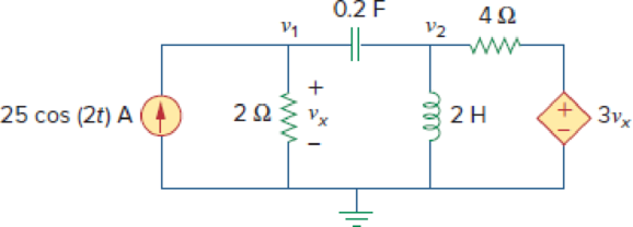
Figure 10.3
Answer: v1(t) = 28.31 cos (2t + 60.01°) V, v2(t) = 82.56 cos(2t + 57.12°) V.
Expert Solution & Answer
Want to see the full answer?
Check out a sample textbook solution
Students have asked these similar questions
".I need the correct answers with explanations"
Q1: What is the orientation of voltage regulation value (positive or negative) of
alternator loaded by capacitive load? Explain the effect of armature reaction on
voltage regulation for this load? Draw the load characteristics of alternator for
capacitive, inductive, and inductive loads?
Q2: A 2000 kVA,2200 V, 60 Hz,Y-connected alternator has a resistance of 0.25
between each pair of terminal. A field current of 80 A produces a short circuit current equal to full load
current in each line. The same field current produces an e.m.f of 800 V(L-L) on open circuit .Determine the full
load voltage regulation of alternator at unity p.f?
12. If the length of a transmission line increases, its inductance is
B. decreases
C. Constant
D. None of them
A. increases
13. When the regulation is negative, then receiving end voltage (VR) is.......... than sending and voltage (VS).
B. More
C. Equal
A. Less
D. None of the them
10. If the spacing between the conductors is decrease, the inductance of the line will be:
A. Increase B. decreases C. Not effected
D. Non of them
6. Cables have more effective in...
A. Inductance
B. Capacitance
than over head transmission lines
C. Resistance
D. All of the abov
7. By which of the following methods string efficiency can be equa! 100%
A. Using a guard ring B. Equal insulator voltage C. Using long cross arm D.Non of them
Power system
Prove answer
".I need the correct answers with explanations"
A power station has a daily load cycle as under: 260 kwh for 6 hours; 200 kwh for 8 hours: 160 kwh for 4
hours, 100 kwh for 6 hours. If the power station is equipped with 4 units of 75 kw each, calculate (i) daily load
factor (ii) plant capacity factor and (iii) daily requirement of fuel in kg if the calorific value of fuel used were
10,000 kcal/kg.
Chapter 10 Solutions
Fundamentals of Electric Circuits
Ch. 10.2 - Using nodal analysis, find v1 and v2 is in the...Ch. 10.2 - Calculate V1 and V2 in the circuit shown in Fig....Ch. 10.3 - Find Io in Fig. 10.8 using mesh analysis. Figure...Ch. 10.3 - Figure 10.11 For Practice Prob. 10.4. Calculate...Ch. 10.4 - Find current Io in the circuit of Fig. 10.8 using...Ch. 10.4 - Calculate vo in the circuit of Fig. 10.15 using...Ch. 10.6 - Determine the Norton equivalent of the circuit in...Ch. 10.7 - Find vo and io in the op amp circuit of Fig....Ch. 10.7 - Obtain the closed-loop gain and phase shift for...Ch. 10.8 - Use PSpice to obtain vo and io in the circuit of...
Ch. 10.8 - Obtain Vx and Ix in the circuit depicted in Fig....Ch. 10.9 - Determine the equivalent capacitance of the op amp...Ch. 10.9 - In the Wien-bridge oscillator circuit in Fig....Ch. 10 - The voltage Vo across the capacitor in Fig. 10.43...Ch. 10 - The value of the current Io in the circuit of Fig....Ch. 10 - Using nodal analysis, the value of Vo in the...Ch. 10 - In the circuit of Fig. 10.46, current i(t) is: (a)...Ch. 10 - Refer to the circuit in Fig. 10.47 and observe...Ch. 10 - For the circuit in Fig. 10.48, the Thevenin...Ch. 10 - In the circuit of Fig. 10.48, the Thevenin voltage...Ch. 10 - Refer to the circuit in Fig. 10.49. The Norton...Ch. 10 - Figure 10.49 For Review Questions 10.8 and 10.9....Ch. 10 - PSpice can handle a circuit with two independent...Ch. 10 - Determine i in the circuit of Fig. 10.50. Figure...Ch. 10 - Using Fig. 10.51, design a problem to help other...Ch. 10 - Determine vo in the circuit of Fig. 10.52. Figure...Ch. 10 - Compute vo(t) in the circuit of Fig. 10.53. Figure...Ch. 10 - Find io in the circuit of Fig. 10.54.Ch. 10 - Determine Vx in Fig. 10.55. Figure 10.55 For Prob....Ch. 10 - Use nodal analysis to find V in the circuit of...Ch. 10 - Use nodal analysis to find current io in the...Ch. 10 - Use nodal analysis to find vo in the circuit of...Ch. 10 - Use nodal analysis to find vo in the circuit of...Ch. 10 - Using nodal analysis, find io(t) in the circuit in...Ch. 10 - Using Fig. 10.61, design a problem to help other...Ch. 10 - Determine Vx in the circuit of Fig. 10.62 using...Ch. 10 - Calculate the voltage at nodes 1 and 2 in the...Ch. 10 - Solve for the current I in the circuit of Fig....Ch. 10 - Use nodal analysis to find Vx in the circuit shown...Ch. 10 - By nodal analysis, obtain current Io in the...Ch. 10 - Use nodal analysis to obtain Vo in the circuit of...Ch. 10 - Obtain Vo in Fig. 10.68 using nodal analysis.Ch. 10 - Refer to Fig. 10.69. If vs (t) = Vm sin t and vo...Ch. 10 - For each of the circuits in Fig. 10.70, find Vo/Vi...Ch. 10 - For the circuit in Fig. 10.71, determine Vo/Vs....Ch. 10 - Using nodal analysis obtain V in the circuit of...Ch. 10 - Design a problem to help other students better...Ch. 10 - Solve for io in Fig. 10.73 using mesh analysis....Ch. 10 - Use mesh analysis to find current io in the...Ch. 10 - Using mesh analysis, find I1 and I2 in the circuit...Ch. 10 - In the circuit of Fig. 10.76, determine the mesh...Ch. 10 - Using Fig. 10.77, design a problem help other...Ch. 10 - Use mesh analysis to find vo in the circuit of...Ch. 10 - Use mesh analysis to determine current Io in the...Ch. 10 - Determine Vo and Io in the circuit of Fig. 10.80...Ch. 10 - Compute I in Prob. 10.15 using mesh analysis....Ch. 10 - Use mesh analysis to find Io in Fig. 10.28 (for...Ch. 10 - Calculate Io in Fig. 10.30 (for Practice Prob....Ch. 10 - Compute Vo in the circuit of Fig. 10.81 using mesh...Ch. 10 - Use mesh analysis to find currents I1, I2, and I3...Ch. 10 - Using mesh analysis, obtain Io in the circuit...Ch. 10 - Find I1, I2, I3, and Ix in the circuit of Fig....Ch. 10 - Find io in the circuit shown in Fig. 10.85 using...Ch. 10 - Find vo for the circuit in Fig. 10.86, assuming...Ch. 10 - Using Fig. 10.87, design a problem to help other...Ch. 10 - Using the superposition principle, find ix in the...Ch. 10 - Use the superposition principle to obtain vx in...Ch. 10 - Use superposition to find i(t) in the circuit of...Ch. 10 - Solve for vo(t) in the circuit of Fig. 10.91 using...Ch. 10 - Determine io in the circuit of Fig. 10.92, using...Ch. 10 - Find io in the circuit of Fig. 10.93 using...Ch. 10 - Using source transformation, find i in the circuit...Ch. 10 - Using Fig. 10.95, design a problem to help other...Ch. 10 - Use source transformation to find Io in the...Ch. 10 - Use the concept of source transformation to find...Ch. 10 - Rework Prob. 10.7 using source transformation. Use...Ch. 10 - Find the Thevenin and Norton equivalent circuits...Ch. 10 - For each of the circuits in Fig. 10.99, obtain...Ch. 10 - Using Fig. 10.100, design a problem to help other...Ch. 10 - For the circuit depicted in Fig. 10.101, find the...Ch. 10 - Calculate the output impedance of the circuit...Ch. 10 - Find the Thevenin equivalent of the circuit in...Ch. 10 - Using Thevenins theorem, find vo in the circuit of...Ch. 10 - Obtain the Norton equivalent of the circuit...Ch. 10 - For the circuit shown in Fig. 10.107, find the...Ch. 10 - Using Fig. 10.108, design a problem to help other...Ch. 10 - At terminals a-b, obtain Thevenin and Norton...Ch. 10 - Find the Thevenin and Norton equivalent circuits...Ch. 10 - Find the Thevenin equivalent at terminals ab in...Ch. 10 - For the integrator shown in Fig. 10.112, obtain...Ch. 10 - Using Fig. 10.113, design a problem to help other...Ch. 10 - Find vo in the op amp circuit of Fig. 10.114....Ch. 10 - Compute io(t) in the op amp circuit in Fig. 10.115...Ch. 10 - If the input impedance is defined as Zin = Vs/Is,...Ch. 10 - Evaluate the voltage gain Av = Vo/Vs in the op amp...Ch. 10 - In the op amp circuit of Fig. 10.118, find the...Ch. 10 - Determine Vo and Io in the op amp circuit of Fig....Ch. 10 - Compute the closed-loop gain Vo/Vs for the op amp...Ch. 10 - Determine vo(t) in the op amp circuit in Fig....Ch. 10 - For the op amp circuit in Fig. 10.122, obtain Vo....Ch. 10 - Obtain vo(t) for the op amp circuit in Fig. 10.123...Ch. 10 - Use PSpice or MultiSim to determine Vo in the...Ch. 10 - Solve Prob. 10.19 using PSpice or MultiSim. Obtain...Ch. 10 - Use PSpice or MultiSim to find vo(t) in the...Ch. 10 - Obtain Vo in the circuit of Fig. 10.126 using...Ch. 10 - Using Fig. 10.127, design a problem to help other...Ch. 10 - Use PSpice or MultiSim to find V1, V2, and V3 in...Ch. 10 - Determine V1, V2, and V3 in the circuit of Fig....Ch. 10 - Use PSpice or MultiSim to find vo and io in the...Ch. 10 - The op amp circuit in Fig. 10.131 is called an...Ch. 10 - Figure 10.132 shows a Wien-bridge network. Show...Ch. 10 - Consider the oscillator in Fig. 10.133. (a)...Ch. 10 - The oscillator circuit in Fig. 10.134 uses an...Ch. 10 - Figure 10.135 shows a Colpitts oscillator. Show...Ch. 10 - Design a Colpitts oscillator that will operate at...Ch. 10 - Figure 10.136 shows a Hartley oscillator. Show...Ch. 10 - Refer to the oscillator in Fig. 10.137. (a) Show...
Knowledge Booster


Learn more about
Need a deep-dive on the concept behind this application? Look no further. Learn more about this topic, electrical-engineering and related others by exploring similar questions and additional content below.Similar questions
- "I need the correct answers with explanations" Pick up the correct answer 1. The area under the daily load curve gives A. average load in kw B. units generated in kwh 2. the minimum phase-neutral voltage at which corona A. Visual critical voltage B. Receiving voltage C. plant capacity in kw D. Maximum demand in kw occurs is C. String voltage D. Critical disruptive voltage. 3. If the length of a transmission line increases, its inductance is B. Decreases C. Constant A. Increases 4. Photo cells are connected in parallel in order to D. None of them A. Increase voltage rating B. Increase current rating C. Increase life cells. D. All of the them 5. Which of the following is a high head turbine? A. Pelton turbine B. Francis turbine 6. Best diversity factor will be at: C. Kaplan turbine D. Propeller turbine A. diversity factor 1 7. When the voltage regulation is positive, then receiving voltage is ...... than sending voltage A. Less B. More C. Equal D. None of the them 8. Fill factor of solar…arrow_forwardConsider the system shown in Fig. Q4(b). Draw a Bode diagram of the open-loop transfer function, and determine the value of the gain K such that the phase margin is 50° . Also, obtain the gain margin of the system with the determined value of gainarrow_forward".I need the correct answers with explanations" Answer True or False and correct errors if found 1. In a certain Op-Amp. if Ad-3500, Ac-0.35, the CMRR=100dB. 2. The voltage series feedback can increase both input and output impedances. 3. A two-pole Sallen-Key high-pass filter contains one capacitor and two resistors. 4. The main feature of a crystal oscillator is the high frequency operation. Each transistor in a class B power amplifier conducts for the entire input cycle. The Q-point must be centered on the load line for maximum class A output signal swing. 7. The differentiator Op-Amp can convert the triangle waveform into sinewave. Class AB power amplifier eliminates crossover distortion found in pure class A. 9. Wien-bridge oscillators are based on positive feedback circuits. 10. The band-reject filter is composed of multiplication of LPF and HPF.arrow_forward
- ".I need the correct answers with explanations" Pick up the correct answer 1. Station that contain boiler is: A. hydro station B. Diesel station 2. Taking into account cost, most of the D. All of them C. Steam power station high-voltage transmission lines are OC. Either of the above D. None of the ab 3. If the maximum load is equal to plant capacity. The plant capacity factor is: A. Underground. B. Overhead C. >1 D. <1 A. 1 4. Five photocells are connected in parallel, 2V for each cell. The output voltage is A.2.5 V B. zero B. 10 V C.2V) D. 5 V 5. Sum of continuous ratings of all the equipment connected to electric power system is defined as: A. Maximum demand B. Connected load C. Daily average load D. Load variation 6. Cables have more effective in.............. than over head transmission lines B. Capacitance C. Resistance D. All of the abov A. Inductance 7. By which of the following methods string efficiency can be equal. 100% A. Using a guard ring B. Equal insulator voltage C.…arrow_forwardQ3/A unity-feedback system with the forward transfer function G(S)= K S(S+7) is operating with a closed-loop step response that has 15% overshoot. Do the following: a. Evaluate the steady-state error for a unit ramp input. b. Design a lag compensator to improve the steady-state error by a factor of 20 to get a new dominant closed-loop poles S-3.4+ j5.63. place the pole of the lag compensator at s=-0.01 c. Design a lag compensator using OP amp if R1= 100KS2 R2=10 KS2 and R3= 10Karrow_forwardplease explain and draw the graphs clearly, I am most confused with the graphs thanksarrow_forward
- please show step by step and explain clearlyarrow_forwardPlease solve this question step by step handwritten solution and do not use ai or chat gpt please thank youarrow_forwardFind the mathematical expression in fourier series for this output below shown in the image. This must have the terms ao, ak and bkarrow_forward
- Please solve this question step by step handwritten solution and do not use ai or chat gpt please thank youarrow_forwardPlease solve this question step by step hand written solution and do not use ai or chat gpt thank youarrow_forwardPlease solve this question handwritten, step by step showing details and no ai or chat gpt solution please thank youarrow_forward
arrow_back_ios
SEE MORE QUESTIONS
arrow_forward_ios
Recommended textbooks for you
 Introductory Circuit Analysis (13th Edition)Electrical EngineeringISBN:9780133923605Author:Robert L. BoylestadPublisher:PEARSON
 Delmar's Standard Textbook Of ElectricityElectrical EngineeringISBN:9781337900348Author:Stephen L. HermanPublisher:Cengage Learning
 Programmable Logic ControllersElectrical EngineeringISBN:9780073373843Author:Frank D. PetruzellaPublisher:McGraw-Hill Education
 Fundamentals of Electric CircuitsElectrical EngineeringISBN:9780078028229Author:Charles K Alexander, Matthew SadikuPublisher:McGraw-Hill Education
 Electric Circuits. (11th Edition)Electrical EngineeringISBN:9780134746968Author:James W. Nilsson, Susan RiedelPublisher:PEARSON
 Engineering ElectromagneticsElectrical EngineeringISBN:9780078028151Author:Hayt, William H. (william Hart), Jr, BUCK, John A.Publisher:Mcgraw-hill Education,
Introductory Circuit Analysis (13th Edition)
Electrical Engineering
ISBN:9780133923605
Author:Robert L. Boylestad
Publisher:PEARSON
Delmar's Standard Textbook Of Electricity
Electrical Engineering
ISBN:9781337900348
Author:Stephen L. Herman
Publisher:Cengage Learning
Programmable Logic Controllers
Electrical Engineering
ISBN:9780073373843
Author:Frank D. Petruzella
Publisher:McGraw-Hill Education
Fundamentals of Electric Circuits
Electrical Engineering
ISBN:9780078028229
Author:Charles K Alexander, Matthew Sadiku
Publisher:McGraw-Hill Education
Electric Circuits. (11th Edition)
Electrical Engineering
ISBN:9780134746968
Author:James W. Nilsson, Susan Riedel
Publisher:PEARSON
Engineering Electromagnetics
Electrical Engineering
ISBN:9780078028151
Author:Hayt, William H. (william Hart), Jr, BUCK, John A.
Publisher:Mcgraw-hill Education,
Nodal Analysis for Circuits Explained; Author: Engineer4Free;https://www.youtube.com/watch?v=f-sbANgw4fo;License: Standard Youtube License