Concept explainers
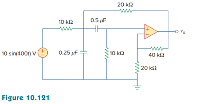
Determine vo(t) in the op amp circuit in Fig. 10.121 below.

Calculate the output voltage
Answer to Problem 78P
The value of output voltage
Explanation of Solution
Given data:
Refer to Figure 10.121 in the textbook for op amp circuit.
Formula used:
Write the expression to calculate impedance of the capacitor.
Here,
Write the general representation of sinusoidal sine function.
Here,
Write the general expression to phasor transform of sinusoidal function from time domain to frequency domain.
Here,
Write the polar form representation of frequency domain.
Calculation:
Comparing
Substitute
Substitute
Substitute
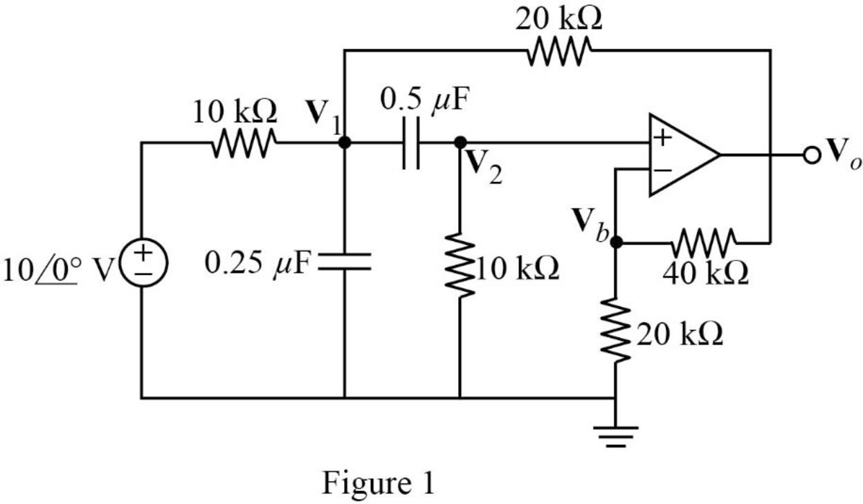
The frequency domain representation of given figure is shown in Figure 1.

Apply Kirchhoff’s current law at node
Simplify the equation as follows.
Apply Kirchhoff’s current law at node
Apply voltage division rule at node
According to the properties of ideal op amp, the voltage at the input of the non-inverting terminal of the op amp is equal to the voltage at the input of the inverting terminal. Hence,
Substitute equation (5) in (1).
Substitute equation (5) in (2).
Represent the equations (6) and (7) in matrix form.
Write the MATLAB code to solve equation (8) to find
A = [3+6*1i -1-1.333*1i; 1 -0.3333+0.1666*1i];
b = [20; 0];
x = A\b
The MATLAB result is shown below.
x =
5.9463 - 4.3272i 19.4666 - 3.2525i
The polar representation of obtained result is shown below.
Represent the output voltage in time domain.
Conclusion:
Thus, the value of output voltage
Want to see more full solutions like this?
Chapter 10 Solutions
Fundamentals of Electric Circuits
- find the inverse Laplace transform of X(s)= i) Re[s]> 3 ii) Re[s]<1 s+5 for (s-1)(s-2)(s-3) iii) 1arrow_forwardFor R1, what is the resistance in kΩ? For R1, what the current in mA? For R1, what is the voltage in V? For R1, what is the power in W? For R2, what is the resistance in kΩ? For R2, what the current in mA? For R2, what is the voltage in V? For R2, what is the power in W? For R3, what is the resistance in kΩ? For R3, what the current in mA? For R3, what is the voltage in V? For R3, what is the power in W? For R4, what is the resistance in kΩ? For R4, what the current in mA? For R4, what is the voltage in V? For R4, what is the power in W? For R5, what is the resistance in kΩ? For R5, what the current in mA? For R5, what is the voltage in V? For R5, what is the power in W? What is the total resistance in Ω? What is the total current in mA? What is the total voltage in V? What is the total power in W?arrow_forwardPlease answer allarrow_forwardarrow_back_iosSEE MORE QUESTIONSarrow_forward_ios
 Delmar's Standard Textbook Of ElectricityElectrical EngineeringISBN:9781337900348Author:Stephen L. HermanPublisher:Cengage Learning
