
Fundamentals of Electric Circuits
6th Edition
ISBN: 9780078028229
Author: Charles K Alexander, Matthew Sadiku
Publisher: McGraw-Hill Education
expand_more
expand_more
format_list_bulleted
Concept explainers
Videos
Textbook Question
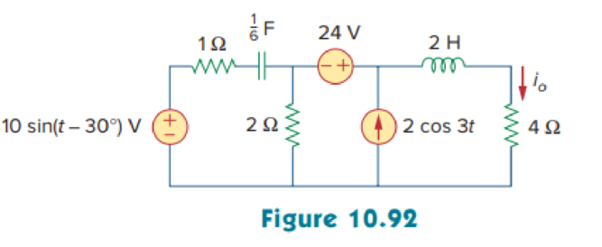
Chapter 10, Problem 47P
Determine io in the circuit of Fig. 10.92, using the superposition principle.
Expert Solution & Answer
Want to see the full answer?
Check out a sample textbook solution
Students have asked these similar questions
Q1: Design a logic circuit for the finite-state machine described by the assigned
table in Fig. 1:
Using D flip-flops.
a.
b.
Using T flip-flops.
Present
Next State
Output
State
x=0
x=0
YE
Y₁Y
Y₁Y
Z
00
00
01
0
0
от
00
0
0
10
00
10
11
00
10
0
Find Va and Vb using mesh analysis
Find Va and Vb using Mesh analysis
Chapter 10 Solutions
Fundamentals of Electric Circuits
Ch. 10.2 - Using nodal analysis, find v1 and v2 is in the...Ch. 10.2 - Calculate V1 and V2 in the circuit shown in Fig....Ch. 10.3 - Find Io in Fig. 10.8 using mesh analysis. Figure...Ch. 10.3 - Figure 10.11 For Practice Prob. 10.4. Calculate...Ch. 10.4 - Find current Io in the circuit of Fig. 10.8 using...Ch. 10.4 - Calculate vo in the circuit of Fig. 10.15 using...Ch. 10.6 - Determine the Norton equivalent of the circuit in...Ch. 10.7 - Find vo and io in the op amp circuit of Fig....Ch. 10.7 - Obtain the closed-loop gain and phase shift for...Ch. 10.8 - Use PSpice to obtain vo and io in the circuit of...
Ch. 10.8 - Obtain Vx and Ix in the circuit depicted in Fig....Ch. 10.9 - Determine the equivalent capacitance of the op amp...Ch. 10.9 - In the Wien-bridge oscillator circuit in Fig....Ch. 10 - The voltage Vo across the capacitor in Fig. 10.43...Ch. 10 - The value of the current Io in the circuit of Fig....Ch. 10 - Using nodal analysis, the value of Vo in the...Ch. 10 - In the circuit of Fig. 10.46, current i(t) is: (a)...Ch. 10 - Refer to the circuit in Fig. 10.47 and observe...Ch. 10 - For the circuit in Fig. 10.48, the Thevenin...Ch. 10 - In the circuit of Fig. 10.48, the Thevenin voltage...Ch. 10 - Refer to the circuit in Fig. 10.49. The Norton...Ch. 10 - Figure 10.49 For Review Questions 10.8 and 10.9....Ch. 10 - PSpice can handle a circuit with two independent...Ch. 10 - Determine i in the circuit of Fig. 10.50. Figure...Ch. 10 - Using Fig. 10.51, design a problem to help other...Ch. 10 - Determine vo in the circuit of Fig. 10.52. Figure...Ch. 10 - Compute vo(t) in the circuit of Fig. 10.53. Figure...Ch. 10 - Find io in the circuit of Fig. 10.54.Ch. 10 - Determine Vx in Fig. 10.55. Figure 10.55 For Prob....Ch. 10 - Use nodal analysis to find V in the circuit of...Ch. 10 - Use nodal analysis to find current io in the...Ch. 10 - Use nodal analysis to find vo in the circuit of...Ch. 10 - Use nodal analysis to find vo in the circuit of...Ch. 10 - Using nodal analysis, find io(t) in the circuit in...Ch. 10 - Using Fig. 10.61, design a problem to help other...Ch. 10 - Determine Vx in the circuit of Fig. 10.62 using...Ch. 10 - Calculate the voltage at nodes 1 and 2 in the...Ch. 10 - Solve for the current I in the circuit of Fig....Ch. 10 - Use nodal analysis to find Vx in the circuit shown...Ch. 10 - By nodal analysis, obtain current Io in the...Ch. 10 - Use nodal analysis to obtain Vo in the circuit of...Ch. 10 - Obtain Vo in Fig. 10.68 using nodal analysis.Ch. 10 - Refer to Fig. 10.69. If vs (t) = Vm sin t and vo...Ch. 10 - For each of the circuits in Fig. 10.70, find Vo/Vi...Ch. 10 - For the circuit in Fig. 10.71, determine Vo/Vs....Ch. 10 - Using nodal analysis obtain V in the circuit of...Ch. 10 - Design a problem to help other students better...Ch. 10 - Solve for io in Fig. 10.73 using mesh analysis....Ch. 10 - Use mesh analysis to find current io in the...Ch. 10 - Using mesh analysis, find I1 and I2 in the circuit...Ch. 10 - In the circuit of Fig. 10.76, determine the mesh...Ch. 10 - Using Fig. 10.77, design a problem help other...Ch. 10 - Use mesh analysis to find vo in the circuit of...Ch. 10 - Use mesh analysis to determine current Io in the...Ch. 10 - Determine Vo and Io in the circuit of Fig. 10.80...Ch. 10 - Compute I in Prob. 10.15 using mesh analysis....Ch. 10 - Use mesh analysis to find Io in Fig. 10.28 (for...Ch. 10 - Calculate Io in Fig. 10.30 (for Practice Prob....Ch. 10 - Compute Vo in the circuit of Fig. 10.81 using mesh...Ch. 10 - Use mesh analysis to find currents I1, I2, and I3...Ch. 10 - Using mesh analysis, obtain Io in the circuit...Ch. 10 - Find I1, I2, I3, and Ix in the circuit of Fig....Ch. 10 - Find io in the circuit shown in Fig. 10.85 using...Ch. 10 - Find vo for the circuit in Fig. 10.86, assuming...Ch. 10 - Using Fig. 10.87, design a problem to help other...Ch. 10 - Using the superposition principle, find ix in the...Ch. 10 - Use the superposition principle to obtain vx in...Ch. 10 - Use superposition to find i(t) in the circuit of...Ch. 10 - Solve for vo(t) in the circuit of Fig. 10.91 using...Ch. 10 - Determine io in the circuit of Fig. 10.92, using...Ch. 10 - Find io in the circuit of Fig. 10.93 using...Ch. 10 - Using source transformation, find i in the circuit...Ch. 10 - Using Fig. 10.95, design a problem to help other...Ch. 10 - Use source transformation to find Io in the...Ch. 10 - Use the concept of source transformation to find...Ch. 10 - Rework Prob. 10.7 using source transformation. Use...Ch. 10 - Find the Thevenin and Norton equivalent circuits...Ch. 10 - For each of the circuits in Fig. 10.99, obtain...Ch. 10 - Using Fig. 10.100, design a problem to help other...Ch. 10 - For the circuit depicted in Fig. 10.101, find the...Ch. 10 - Calculate the output impedance of the circuit...Ch. 10 - Find the Thevenin equivalent of the circuit in...Ch. 10 - Using Thevenins theorem, find vo in the circuit of...Ch. 10 - Obtain the Norton equivalent of the circuit...Ch. 10 - For the circuit shown in Fig. 10.107, find the...Ch. 10 - Using Fig. 10.108, design a problem to help other...Ch. 10 - At terminals a-b, obtain Thevenin and Norton...Ch. 10 - Find the Thevenin and Norton equivalent circuits...Ch. 10 - Find the Thevenin equivalent at terminals ab in...Ch. 10 - For the integrator shown in Fig. 10.112, obtain...Ch. 10 - Using Fig. 10.113, design a problem to help other...Ch. 10 - Find vo in the op amp circuit of Fig. 10.114....Ch. 10 - Compute io(t) in the op amp circuit in Fig. 10.115...Ch. 10 - If the input impedance is defined as Zin = Vs/Is,...Ch. 10 - Evaluate the voltage gain Av = Vo/Vs in the op amp...Ch. 10 - In the op amp circuit of Fig. 10.118, find the...Ch. 10 - Determine Vo and Io in the op amp circuit of Fig....Ch. 10 - Compute the closed-loop gain Vo/Vs for the op amp...Ch. 10 - Determine vo(t) in the op amp circuit in Fig....Ch. 10 - For the op amp circuit in Fig. 10.122, obtain Vo....Ch. 10 - Obtain vo(t) for the op amp circuit in Fig. 10.123...Ch. 10 - Use PSpice or MultiSim to determine Vo in the...Ch. 10 - Solve Prob. 10.19 using PSpice or MultiSim. Obtain...Ch. 10 - Use PSpice or MultiSim to find vo(t) in the...Ch. 10 - Obtain Vo in the circuit of Fig. 10.126 using...Ch. 10 - Using Fig. 10.127, design a problem to help other...Ch. 10 - Use PSpice or MultiSim to find V1, V2, and V3 in...Ch. 10 - Determine V1, V2, and V3 in the circuit of Fig....Ch. 10 - Use PSpice or MultiSim to find vo and io in the...Ch. 10 - The op amp circuit in Fig. 10.131 is called an...Ch. 10 - Figure 10.132 shows a Wien-bridge network. Show...Ch. 10 - Consider the oscillator in Fig. 10.133. (a)...Ch. 10 - The oscillator circuit in Fig. 10.134 uses an...Ch. 10 - Figure 10.135 shows a Colpitts oscillator. Show...Ch. 10 - Design a Colpitts oscillator that will operate at...Ch. 10 - Figure 10.136 shows a Hartley oscillator. Show...Ch. 10 - Refer to the oscillator in Fig. 10.137. (a) Show...
Additional Engineering Textbook Solutions
Find more solutions based on key concepts
Comprehension Check 7-14
The power absorbed by a resistor can be given by P = I2R, where P is power in units of...
Thinking Like an Engineer: An Active Learning Approach (4th Edition)
A byte is made up of eight a. CPUs b. addresses c. variables d. bits
Starting Out with Java: From Control Structures through Objects (7th Edition) (What's New in Computer Science)
The job of the _____ is to fetch instructions, carry out the operations commanded by the instructions, and prod...
Starting Out With Visual Basic (8th Edition)
What are the design issues for character string types?
Concepts Of Programming Languages
This optional Google account security feature sends you a message with a code that you must enter, in addition ...
SURVEY OF OPERATING SYSTEMS
3.3 It is known that a vertical force of 200 lb is required to remove the nail at C from the board. As the nail...
Vector Mechanics for Engineers: Statics
Knowledge Booster


Learn more about
Need a deep-dive on the concept behind this application? Look no further. Learn more about this topic, electrical-engineering and related others by exploring similar questions and additional content below.Similar questions
- Find Va and Vb using nodal analysisarrow_forward2. Using the approximate method, hand sketch the Bode plot for the following transfer functions. a) H(s) = 10 b) H(s) (s+1) c) H(s): = 1 = +1 100 1000 (s+1) 10(s+1) d) H(s) = (s+100) (180+1)arrow_forwardQ4: Write VHDL code to implement the finite-state machine described by the state Diagram in Fig. 1. Fig. 1arrow_forward
- 1. Consider the following feedback system. Bode plot of G(s) is shown below. Phase (deg) Magnitude (dB) -50 -100 -150 -200 0 -90 -180 -270 101 System: sys Frequency (rad/s): 0.117 Magnitude (dB): -74 10° K G(s) Bode Diagram System: sys Frequency (rad/s): 36.8 Magnitude (dB): -99.7 System: sys Frequency (rad/s): 20 Magnitude (dB): -89.9 System: sys Frequency (rad/s): 20 Phase (deg): -143 System: sys Frequency (rad/s): 36.8 Phase (deg): -180 101 Frequency (rad/s) a) Determine the range of K for which the closed-loop system is stable. 102 10³ b) If we want the gain margin to be exactly 50 dB, what is value for K we should choose? c) If we want the phase margin to be exactly 37°, what is value of K we should choose? What will be the corresponding rise time (T) for step-input? d) If we want steady-state error of step input to be 0.6, what is value of K we should choose?arrow_forward: Write VHDL code to implement the finite-state machine/described by the state Diagram in Fig. 4. X=1 X=0 solo X=1 X=0 $1/1 X=0 X=1 X=1 52/2 $3/3 X=1 Fig. 4 X=1 X=1 56/6 $5/5 X=1 54/4 X=0 X-O X=O 5=0 57/7arrow_forwardQuestions: Q1: Verify that the average power generated equals the average power absorbed using the simulated values in Table 7-2. Q2: Verify that the reactive power generated equals the reactive power absorbed using the simulated values in Table 7-2. Q3: Why it is important to correct the power factor of a load? Q4: Find the ideal value of the capacitor theoretically that will result in unity power factor. Vs pp (V) VRIPP (V) VRLC PP (V) AT (μs) T (us) 8° pf Simulated 14 8.523 7.84 84.850 1000 29.88 0.866 Measured 14 8.523 7.854 82.94 1000 29.85 0.86733 Table 7-2 Power Calculations Pvs (mW) Qvs (mVAR) PRI (MW) Pay (mW) Qt (mVAR) Qc (mYAR) Simulated -12.93 -7.428 9.081 3.855 12.27 -4.84 Calculated -12.936 -7.434 9.083 3.856 12.32 -4.85 Part II: Power Factor Correction Table 7-3 Power Factor Correction AT (us) 0° pf Simulated 0 0 1 Measured 0 0 1arrow_forward
- Questions: Q1: Verify that the average power generated equals the average power absorbed using the simulated values in Table 7-2. Q2: Verify that the reactive power generated equals the reactive power absorbed using the simulated values in Table 7-2. Q3: Why it is important to correct the power factor of a load? Q4: Find the ideal value of the capacitor theoretically that will result in unity power factor. Vs pp (V) VRIPP (V) VRLC PP (V) AT (μs) T (us) 8° pf Simulated 14 8.523 7.84 84.850 1000 29.88 0.866 Measured 14 8.523 7.854 82.94 1000 29.85 0.86733 Table 7-2 Power Calculations Pvs (mW) Qvs (mVAR) PRI (MW) Pay (mW) Qt (mVAR) Qc (mYAR) Simulated -12.93 -7.428 9.081 3.855 12.27 -4.84 Calculated -12.936 -7.434 9.083 3.856 12.32 -4.85 Part II: Power Factor Correction Table 7-3 Power Factor Correction AT (us) 0° pf Simulated 0 0 1 Measured 0 0 1arrow_forwardelectric plants. Prepare the load schedulearrow_forwardelectric plants Draw the column diagram. Calculate the voltage drop. by hand writingarrow_forward
- electric plants. Draw the lighting, socket, telephone, TV, and doorbell installations on the given single-story project with an architectural plan by hand writingarrow_forwardA circularly polarized wave, traveling in the +z-direction, is received by an elliptically polarized antenna whose reception characteristics near the main lobe are given approx- imately by E„ = [2â, + jâ‚]ƒ(r. 8, 4) Find the polarization loss factor PLF (dimensionless and in dB) when the incident wave is (a) right-hand (CW) An elliptically polarized wave traveling in the negative z-direction is received by a circularly polarized antenna. The vector describing the polarization of the incident wave is given by Ei= 2ax + jay.Find the polarization loss factor PLF (dimensionless and in dB) when the wave that would be transmitted by the antenna is (a) right-hand CParrow_forwardjX(1)=j0.2p.u. jXa(2)=j0.15p.u. jxa(0)=0.15 p.u. V₁=1/0°p.u. V₂=1/0° p.u. 1 jXr(1) = j0.15 p.11. jXT(2) = j0.15 p.u. jXr(0) = j0.15 p.u. V3=1/0° p.u. А V4=1/0° p.u. 2 jX1(1)=j0.12 p.u. 3 jX2(1)=j0.15 p.u. 4 jX1(2)=0.12 p.11. JX1(0)=0.3 p.u. jX/2(2)=j0.15 p.11. X2(0)=/0.25 p.1. Figure 1. Circuit for Q3 b).arrow_forward
arrow_back_ios
SEE MORE QUESTIONS
arrow_forward_ios
Recommended textbooks for you
 Delmar's Standard Textbook Of ElectricityElectrical EngineeringISBN:9781337900348Author:Stephen L. HermanPublisher:Cengage Learning
Delmar's Standard Textbook Of Electricity
Electrical Engineering
ISBN:9781337900348
Author:Stephen L. Herman
Publisher:Cengage Learning
Current Divider Rule; Author: Neso Academy;https://www.youtube.com/watch?v=hRU1mKWUehY;License: Standard YouTube License, CC-BY