
Fundamentals of Electric Circuits
6th Edition
ISBN: 9780078028229
Author: Charles K Alexander, Matthew Sadiku
Publisher: McGraw-Hill Education
expand_more
expand_more
format_list_bulleted
Concept explainers
Videos
Textbook Question
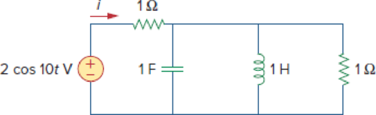
Chapter 10, Problem 1P
Determine i in the circuit of Fig. 10.50.
Figure 10.50
For Prob. 10.1.
Expert Solution & Answer
Want to see the full answer?
Check out a sample textbook solution
Students have asked these similar questions
4. A differential BPSK transmitter consumes 10 W and provides a BER of 1*10^-7. If the system moves
to 16-QAM, what is new minimum transmit power?
5. The noise power (in watts) measured in a 40MHz Wifi channel is 230*10^-6 Watts. The access point
(AP) output power is 600 mW and only uses 256QAM and has a data rate of 400Mbps. The channel
losses can be modeled as 0.4dB/meter. An application on your phone requires a BER of < than 1*10^-4.
A) What is the maximum distance between the AP and your phone?
b) if the AP and my phone could switch to 64QAM and support the same data rate, what is the new
maximum distance between the AP and my phone?
3. You are to design a 9-volt battery operated communication system that has a center frequency of 2.4
GHz. It must last 10 years without replacing batteries. The application requires a BER of <10^-5 and a
data rate of 500bps. The channel can be modeled as AWGN with a noise power spectral density of 10^-
8 W/Hz. (a) What modulation scheme would you use? B) what is the required capacity of the batteries?
and (c) Is the battery commercially available?
Chapter 10 Solutions
Fundamentals of Electric Circuits
Ch. 10.2 - Using nodal analysis, find v1 and v2 is in the...Ch. 10.2 - Calculate V1 and V2 in the circuit shown in Fig....Ch. 10.3 - Find Io in Fig. 10.8 using mesh analysis. Figure...Ch. 10.3 - Figure 10.11 For Practice Prob. 10.4. Calculate...Ch. 10.4 - Find current Io in the circuit of Fig. 10.8 using...Ch. 10.4 - Calculate vo in the circuit of Fig. 10.15 using...Ch. 10.6 - Determine the Norton equivalent of the circuit in...Ch. 10.7 - Find vo and io in the op amp circuit of Fig....Ch. 10.7 - Obtain the closed-loop gain and phase shift for...Ch. 10.8 - Use PSpice to obtain vo and io in the circuit of...
Ch. 10.8 - Obtain Vx and Ix in the circuit depicted in Fig....Ch. 10.9 - Determine the equivalent capacitance of the op amp...Ch. 10.9 - In the Wien-bridge oscillator circuit in Fig....Ch. 10 - The voltage Vo across the capacitor in Fig. 10.43...Ch. 10 - The value of the current Io in the circuit of Fig....Ch. 10 - Using nodal analysis, the value of Vo in the...Ch. 10 - In the circuit of Fig. 10.46, current i(t) is: (a)...Ch. 10 - Refer to the circuit in Fig. 10.47 and observe...Ch. 10 - For the circuit in Fig. 10.48, the Thevenin...Ch. 10 - In the circuit of Fig. 10.48, the Thevenin voltage...Ch. 10 - Refer to the circuit in Fig. 10.49. The Norton...Ch. 10 - Figure 10.49 For Review Questions 10.8 and 10.9....Ch. 10 - PSpice can handle a circuit with two independent...Ch. 10 - Determine i in the circuit of Fig. 10.50. Figure...Ch. 10 - Using Fig. 10.51, design a problem to help other...Ch. 10 - Determine vo in the circuit of Fig. 10.52. Figure...Ch. 10 - Compute vo(t) in the circuit of Fig. 10.53. Figure...Ch. 10 - Find io in the circuit of Fig. 10.54.Ch. 10 - Determine Vx in Fig. 10.55. Figure 10.55 For Prob....Ch. 10 - Use nodal analysis to find V in the circuit of...Ch. 10 - Use nodal analysis to find current io in the...Ch. 10 - Use nodal analysis to find vo in the circuit of...Ch. 10 - Use nodal analysis to find vo in the circuit of...Ch. 10 - Using nodal analysis, find io(t) in the circuit in...Ch. 10 - Using Fig. 10.61, design a problem to help other...Ch. 10 - Determine Vx in the circuit of Fig. 10.62 using...Ch. 10 - Calculate the voltage at nodes 1 and 2 in the...Ch. 10 - Solve for the current I in the circuit of Fig....Ch. 10 - Use nodal analysis to find Vx in the circuit shown...Ch. 10 - By nodal analysis, obtain current Io in the...Ch. 10 - Use nodal analysis to obtain Vo in the circuit of...Ch. 10 - Obtain Vo in Fig. 10.68 using nodal analysis.Ch. 10 - Refer to Fig. 10.69. If vs (t) = Vm sin t and vo...Ch. 10 - For each of the circuits in Fig. 10.70, find Vo/Vi...Ch. 10 - For the circuit in Fig. 10.71, determine Vo/Vs....Ch. 10 - Using nodal analysis obtain V in the circuit of...Ch. 10 - Design a problem to help other students better...Ch. 10 - Solve for io in Fig. 10.73 using mesh analysis....Ch. 10 - Use mesh analysis to find current io in the...Ch. 10 - Using mesh analysis, find I1 and I2 in the circuit...Ch. 10 - In the circuit of Fig. 10.76, determine the mesh...Ch. 10 - Using Fig. 10.77, design a problem help other...Ch. 10 - Use mesh analysis to find vo in the circuit of...Ch. 10 - Use mesh analysis to determine current Io in the...Ch. 10 - Determine Vo and Io in the circuit of Fig. 10.80...Ch. 10 - Compute I in Prob. 10.15 using mesh analysis....Ch. 10 - Use mesh analysis to find Io in Fig. 10.28 (for...Ch. 10 - Calculate Io in Fig. 10.30 (for Practice Prob....Ch. 10 - Compute Vo in the circuit of Fig. 10.81 using mesh...Ch. 10 - Use mesh analysis to find currents I1, I2, and I3...Ch. 10 - Using mesh analysis, obtain Io in the circuit...Ch. 10 - Find I1, I2, I3, and Ix in the circuit of Fig....Ch. 10 - Find io in the circuit shown in Fig. 10.85 using...Ch. 10 - Find vo for the circuit in Fig. 10.86, assuming...Ch. 10 - Using Fig. 10.87, design a problem to help other...Ch. 10 - Using the superposition principle, find ix in the...Ch. 10 - Use the superposition principle to obtain vx in...Ch. 10 - Use superposition to find i(t) in the circuit of...Ch. 10 - Solve for vo(t) in the circuit of Fig. 10.91 using...Ch. 10 - Determine io in the circuit of Fig. 10.92, using...Ch. 10 - Find io in the circuit of Fig. 10.93 using...Ch. 10 - Using source transformation, find i in the circuit...Ch. 10 - Using Fig. 10.95, design a problem to help other...Ch. 10 - Use source transformation to find Io in the...Ch. 10 - Use the concept of source transformation to find...Ch. 10 - Rework Prob. 10.7 using source transformation. Use...Ch. 10 - Find the Thevenin and Norton equivalent circuits...Ch. 10 - For each of the circuits in Fig. 10.99, obtain...Ch. 10 - Using Fig. 10.100, design a problem to help other...Ch. 10 - For the circuit depicted in Fig. 10.101, find the...Ch. 10 - Calculate the output impedance of the circuit...Ch. 10 - Find the Thevenin equivalent of the circuit in...Ch. 10 - Using Thevenins theorem, find vo in the circuit of...Ch. 10 - Obtain the Norton equivalent of the circuit...Ch. 10 - For the circuit shown in Fig. 10.107, find the...Ch. 10 - Using Fig. 10.108, design a problem to help other...Ch. 10 - At terminals a-b, obtain Thevenin and Norton...Ch. 10 - Find the Thevenin and Norton equivalent circuits...Ch. 10 - Find the Thevenin equivalent at terminals ab in...Ch. 10 - For the integrator shown in Fig. 10.112, obtain...Ch. 10 - Using Fig. 10.113, design a problem to help other...Ch. 10 - Find vo in the op amp circuit of Fig. 10.114....Ch. 10 - Compute io(t) in the op amp circuit in Fig. 10.115...Ch. 10 - If the input impedance is defined as Zin = Vs/Is,...Ch. 10 - Evaluate the voltage gain Av = Vo/Vs in the op amp...Ch. 10 - In the op amp circuit of Fig. 10.118, find the...Ch. 10 - Determine Vo and Io in the op amp circuit of Fig....Ch. 10 - Compute the closed-loop gain Vo/Vs for the op amp...Ch. 10 - Determine vo(t) in the op amp circuit in Fig....Ch. 10 - For the op amp circuit in Fig. 10.122, obtain Vo....Ch. 10 - Obtain vo(t) for the op amp circuit in Fig. 10.123...Ch. 10 - Use PSpice or MultiSim to determine Vo in the...Ch. 10 - Solve Prob. 10.19 using PSpice or MultiSim. Obtain...Ch. 10 - Use PSpice or MultiSim to find vo(t) in the...Ch. 10 - Obtain Vo in the circuit of Fig. 10.126 using...Ch. 10 - Using Fig. 10.127, design a problem to help other...Ch. 10 - Use PSpice or MultiSim to find V1, V2, and V3 in...Ch. 10 - Determine V1, V2, and V3 in the circuit of Fig....Ch. 10 - Use PSpice or MultiSim to find vo and io in the...Ch. 10 - The op amp circuit in Fig. 10.131 is called an...Ch. 10 - Figure 10.132 shows a Wien-bridge network. Show...Ch. 10 - Consider the oscillator in Fig. 10.133. (a)...Ch. 10 - The oscillator circuit in Fig. 10.134 uses an...Ch. 10 - Figure 10.135 shows a Colpitts oscillator. Show...Ch. 10 - Design a Colpitts oscillator that will operate at...Ch. 10 - Figure 10.136 shows a Hartley oscillator. Show...Ch. 10 - Refer to the oscillator in Fig. 10.137. (a) Show...
Knowledge Booster


Learn more about
Need a deep-dive on the concept behind this application? Look no further. Learn more about this topic, electrical-engineering and related others by exploring similar questions and additional content below.Similar questions
- Refer to the logic diagram of Figure. Gate 1 and gate 4 belong to the standard TTL family, while gate 2 and gate 3 belong to the Schottky TTL family and the low-power Schottky TTL family respectively. Determine whether the fan-out capability of gate 1 is being exceeded. Relevant data for the three logic families are given in Table 3(a).arrow_forward2. An existing system uses noncoherent BASK. The application requires a BER of <10^-5. The current transmit power is 25 Watts. If the system changes to a coherent BPSK modulation scheme, what is the new transmit power required to deliver the same BER?arrow_forwardfunctions: where are the Cauchy-Riemann equations satisfied by the 1- w = z² - 4 2- w = 7 Z Z+5 3- w = Z-2 z+1arrow_forward
- Find the integral for ezz Cz-i ezz Zdz and $c (z-i)³ dzarrow_forwardDetermine the voltage across A and B in the circuit given below:arrow_forwardAn inductive coil having negligible resistance and 0.1H inductance is connected a supply of 220V, 50 Hz. Calculate (a) Inductive reactance, (b) RMS value of Current, (c) Power consumed, (d) Power factor, (e) Write down the equations for voltage and current.arrow_forward
- If Fourier transform of f(t) is F(w) find Fourier transform of g(t) using only properties. d g(t) = f(2t)+8(3-1)+ ej(t-1)f(t) dtarrow_forward3z²+7z+1 dz (b) If C is the circle |z+i|=1. What is the value of S (a) If C is the circle |z+1|=1. z+1 (c) If C is the ellipse x²+y2=8.arrow_forward= Find the residues of all the poles of f(z) = 3z (z+2)²(z²-1)arrow_forward
arrow_back_ios
SEE MORE QUESTIONS
arrow_forward_ios
Recommended textbooks for you
 Introductory Circuit Analysis (13th Edition)Electrical EngineeringISBN:9780133923605Author:Robert L. BoylestadPublisher:PEARSON
 Delmar's Standard Textbook Of ElectricityElectrical EngineeringISBN:9781337900348Author:Stephen L. HermanPublisher:Cengage Learning
 Programmable Logic ControllersElectrical EngineeringISBN:9780073373843Author:Frank D. PetruzellaPublisher:McGraw-Hill Education
 Fundamentals of Electric CircuitsElectrical EngineeringISBN:9780078028229Author:Charles K Alexander, Matthew SadikuPublisher:McGraw-Hill Education
 Electric Circuits. (11th Edition)Electrical EngineeringISBN:9780134746968Author:James W. Nilsson, Susan RiedelPublisher:PEARSON
 Engineering ElectromagneticsElectrical EngineeringISBN:9780078028151Author:Hayt, William H. (william Hart), Jr, BUCK, John A.Publisher:Mcgraw-hill Education,
Introductory Circuit Analysis (13th Edition)
Electrical Engineering
ISBN:9780133923605
Author:Robert L. Boylestad
Publisher:PEARSON
Delmar's Standard Textbook Of Electricity
Electrical Engineering
ISBN:9781337900348
Author:Stephen L. Herman
Publisher:Cengage Learning
Programmable Logic Controllers
Electrical Engineering
ISBN:9780073373843
Author:Frank D. Petruzella
Publisher:McGraw-Hill Education
Fundamentals of Electric Circuits
Electrical Engineering
ISBN:9780078028229
Author:Charles K Alexander, Matthew Sadiku
Publisher:McGraw-Hill Education
Electric Circuits. (11th Edition)
Electrical Engineering
ISBN:9780134746968
Author:James W. Nilsson, Susan Riedel
Publisher:PEARSON
Engineering Electromagnetics
Electrical Engineering
ISBN:9780078028151
Author:Hayt, William H. (william Hart), Jr, BUCK, John A.
Publisher:Mcgraw-hill Education,
Current Divider Rule; Author: Neso Academy;https://www.youtube.com/watch?v=hRU1mKWUehY;License: Standard YouTube License, CC-BY