
Fox And Mcdonald's Introduction To Fluid Mechanics
9th Edition
ISBN: 9781118921876
Author: Pritchard, Philip J.; Leylegian, John C.; Bhaskaran, Rajesh
Publisher: WILEY
expand_more
expand_more
format_list_bulleted
Concept explainers
Videos
Textbook Question
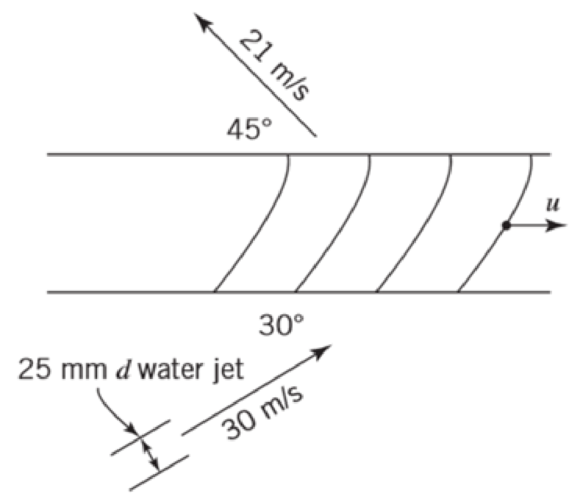
Chapter 10, Problem 71P
The absolute velocities and directions of the jets entering and leaving the blade system are as shown. Calculate the power transferred from the jet to the blade system and the blade angles required.
P10.71
Expert Solution & Answer
Want to see the full answer?
Check out a sample textbook solution
Students have asked these similar questions
The 150-lb skater passes point A with a speed of 6 ft/s.
(Figure 1)
Determine his speed when he reaches point B. Neglect friction.
Determine the normal force exerted on him by the track at this point.
25 ft
B
= 4x
A
20 ft
x
A virtual experiment is designed to determine the effect of friction on the timing and speed
of packages being delivered to a conveyor belt and the normal force applied to the tube.
A package is held and then let go at the edge of a circular shaped tube of radius R = 5m.
The particle at the bottom will transfer to the conveyor belt, as shown below.
Run the simulations for μ = 0, 0.1, 0.2, 0.3, 0.4, 0.5, 0.6 and determine the time and speed at
which the package is delivered to the conveyor belt. In addition, determine the maximum
normal force and its location along the path as measured by angle 0.
Submit in hardcopy form:
(0) Free Body Diagram, equations underneath, derivations
(a) Your MATLAB mfile
(b) A table listing the values in 5 columns:
μ, T (time of transfer), V (speed of transfer), 0 (angle of max N), Nmax (max N)
(c) Based on your results, explain in one sentence what you think will happen to the
package if the friction is increased even further, e.g. μ = 0.8.
NOTE: The ODE is…
Patm = 1 bar
Piston
m = 50 kg
5 g of Air
T₁ = 600 K
P₁ = 3 bar
Stops
A 9.75 x 10⁻³ m²
FIGURE P3.88
Chapter 10 Solutions
Fox And Mcdonald's Introduction To Fluid Mechanics
Ch. 10 - The geometry of a centrifugal water pump is r1 =...Ch. 10 - Find the resulting -groups when (a) D, , and Q or...Ch. 10 - Consider the centrifugal pump impeller dimensions...Ch. 10 - Dimensions of a centrifugal pump impeller areCh. 10 - Dimensions of a centrifugal pump impeller areCh. 10 - The blade is one of a series. Calculate the force...Ch. 10 - This blade is one of a series. What force is...Ch. 10 - A centrifugal water pump, with 15-cm-diameter...Ch. 10 - A centrifugal water pump designed to operate at...Ch. 10 - A series of blades, such as in Example 10.13,...
Ch. 10 - In passing through this blade system, the absolute...Ch. 10 - A centrifugal pump runs at 1750 rpm while pumping...Ch. 10 - A centrifugal water pump designed to operate at...Ch. 10 - Kerosene is pumped by a centrifugal pump. When the...Ch. 10 - In the water pump of Problem 10.8, the pump casing...Ch. 10 - Use data from Appendix C to choose points from the...Ch. 10 - Data from tests of a water suction pump operated...Ch. 10 - A centrifugal pump impeller having r1 = 50 mm, r2...Ch. 10 - A centrifugal pump impeller having dimensions and...Ch. 10 - An axial-flow fan operates in sea-level air at...Ch. 10 - Data measured during tests of a centrifugal pump...Ch. 10 - A small centrifugal pump, when tested at N = 2875...Ch. 10 - If the impeller of Problem 10.20 rotates between...Ch. 10 - At the outlet of a pump impeller of diameter 0.6 m...Ch. 10 - Typical performance curves for a centrifugal pump,...Ch. 10 - A pump with D = 500 mm delivers Q = 0.725 m3/s of...Ch. 10 - At its best efficiency point ( = 0.87), a...Ch. 10 - Using the performance curves in Appendix C, select...Ch. 10 - A pumping system must be specified for a lift...Ch. 10 - A centrifugal water pump operates at 1750 rpm; the...Ch. 10 - A set of eight 30-kW motor-pump units is used to...Ch. 10 - A blower has a rotor with 12-in. outside diameter...Ch. 10 - A centrifugal water pump has an impeller with an...Ch. 10 - Appendix C contains area bound curves for pump...Ch. 10 - Use data from Appendix C to verify the similarity...Ch. 10 - A centrifugal water pump has an impeller with...Ch. 10 - Catalog data for a centrifugal water pump at...Ch. 10 - A 1/3 scale model of a centrifugal water pump...Ch. 10 - Sometimes the variation of water viscosity with...Ch. 10 - A large deep fryer at a snack-food plant contains...Ch. 10 - Data from tests of a pump, with a...Ch. 10 - A four-stage boiler feed pump has suction and...Ch. 10 - A centrifugal pump operating at N = 2265 rpm lifts...Ch. 10 - A centrifugal pump is installed in a piping system...Ch. 10 - Part of the water supply for the South Rim of...Ch. 10 - Consider the flow system shown in Problem 8.94....Ch. 10 - Afire nozzle is supplied through 300 ft of...Ch. 10 - Performance data for a centrifugal fan of 3-ft...Ch. 10 - The performance data of Problem 10.57 are for a...Ch. 10 - Experimental test data for an aircraft engine fuel...Ch. 10 - Preliminary calculations for a hydroelectric power...Ch. 10 - Conditions at the inlet to the nozzle of a Pelton...Ch. 10 - A Francis turbine is to operate under a head of 46...Ch. 10 - A Kaplan (propeller with variable-pitch blades)...Ch. 10 - Francis turbine Units 19, 20, and 21, installed at...Ch. 10 - Measured data for performance of the reaction...Ch. 10 - For a flow rate of 12 L/s and turbine speed of 65...Ch. 10 - The velocity of the water jet driving this impulse...Ch. 10 - An impulse turbine is to develop 15 MW from a...Ch. 10 - An impulse turbine under a net head of 33 ft was...Ch. 10 - The absolute velocities and directions of the jets...Ch. 10 - A fanboat in the Florida Everglades is powered by...Ch. 10 - A jet-propelled aircraft traveling at 225 m/s...Ch. 10 - When an air jet of 1-in.-diameter strikes a series...Ch. 10 - The volume flow rate through the propeller of an...Ch. 10 - A typical American multi blade farm windmill has D...Ch. 10 - An airplane flies at 200 km/h through still air of...Ch. 10 - This ducted propeller unit drives a ship through...Ch. 10 - A model of an American multi blade farm windmill...Ch. 10 - A large Darrieus vertical axis wind turbine was...Ch. 10 - Show that this ducted propeller system when moving...Ch. 10 - This ducted propeller unit (now operating as a...Ch. 10 - What is the maximum power that can be expected...Ch. 10 - If an ideal windmill is operating at best...Ch. 10 - A prototype air compressor with a compression...Ch. 10 - Prob. 89PCh. 10 - We have seen many examples in Chapter 7 of...
Additional Engineering Textbook Solutions
Find more solutions based on key concepts
Write a pseudocode statement that declares the variable total so it can hold integers. Initialize the variable ...
Starting Out with Programming Logic and Design (5th Edition) (What's New in Computer Science)
This type of loop has no way of ending and repeats until the program is interrupted. a. indeterminate b. interm...
Starting Out with Java: From Control Structures through Objects (7th Edition) (What's New in Computer Science)
What common programming language statement, in your opinion, is most detrimental to readability?
Concepts Of Programming Languages
Suppose the Vole memory cells at addresses 0xF0 to 0xF9 contain the bit patterns described in the following tab...
Computer Science: An Overview (13th Edition) (What's New in Computer Science)
In Exercises 41 through 46, identify the errors. Dim9WAsDouble9W=2*9WIstoutput.Items.Add(9W)
Introduction To Programming Using Visual Basic (11th Edition)
How are relationships between tables expressed in a relational database?
Modern Database Management
Knowledge Booster


Learn more about
Need a deep-dive on the concept behind this application? Look no further. Learn more about this topic, mechanical-engineering and related others by exploring similar questions and additional content below.Similar questions
- Assume a Space Launch System (Figure 1(a)) that is approximated as a cantilever undamped single degree of freedom (SDOF) system with a mass at its free end (Figure 1(b)). The cantilever is assumed to be massless. Assume a wind load that is approximated with a concentrated harmonic forcing function p(t) = posin(ωt) acting on the mass. The known properties of the SDOF and the applied forcing function are given below. • Mass of SDOF: m =120 kip/g • Acceleration of gravity: g = 386 in/sec2 • Bending sectional stiffness of SDOF: EI = 1015 lbf×in2 • Height of SDOF: h = 2000 inches • Amplitude of forcing function: po = 6 kip • Forcing frequency: f = 8 Harrow_forwardAssume a Space Launch System (Figure 1(a)) that is approximated as a cantilever undamped single degree of freedom (SDOF) system with a mass at its free end (Figure 1(b)). The cantilever is assumed to be massless. Assume a wind load that is approximated with a concentrated harmonic forcing function p(t) = posin(ωt) acting on the mass. The known properties of the SDOF and the applied forcing function are given below. • Mass of SDOF: m =120 kip/g • Acceleration of gravity: g = 386 in/sec2 • Bending sectional stiffness of SDOF: EI = 1015 lbf×in2 • Height of SDOF: h = 2000 inches • Amplitude of forcing function: po = 6 kip • Forcing frequency: f = 8 Hz Figure 1: Single-degree-of-freedom system in Problem 1. Please compute the following considering the steady-state response of the SDOF system. Do not consider the transient response unless it is explicitly stated in the question. (a) The natural circular frequency and the natural period of the SDOF. (10 points) (b) The maximum displacement of…arrow_forwardAssume a Space Launch System (Figure 1(a)) that is approximated as a cantilever undamped single degree of freedom (SDOF) system with a mass at its free end (Figure 1(b)). The cantilever is assumed to be massless. Assume a wind load that is approximated with a concentrated harmonic forcing function p(t) = posin(ωt) acting on the mass. The known properties of the SDOF and the applied forcing function are given below. • Mass of SDOF: m =120 kip/g • Acceleration of gravity: g = 386 in/sec2 • Bending sectional stiffness of SDOF: EI = 1015 lbf×in2 • Height of SDOF: h = 2000 inches • Amplitude of forcing function: po = 6 kip • Forcing frequency: f = 8 Hz Figure 1: Single-degree-of-freedom system in Problem 1. Please compute the following considering the steady-state response of the SDOF system. Do not consider the transient response unless it is explicitly stated in the question. (a) The natural circular frequency and the natural period of the SDOF. (10 points) (b) The maximum displacement of…arrow_forward
- Please solve 13 * √(2675.16)² + (63.72 + 2255,03)² = 175x106 can you explain the process for getting d seperate thank youarrow_forwardIf the 300-kg drum has a center of mass at point G, determine the horizontal and vertical components of force acting at pin A and the reactions on the smooth pads C and D. The grip at B on member DAB resists both horizontal and vertical components of force at the rim of the drum. P 60 mm; 60 mm: 600 mm A E 30° B C 390 mm 100 mm D Garrow_forwardThe design of the gear-and-shaft system shown requires that steel shafts of the same diameter be used for both AB and CD. It is further required that the angle D through which end D of shaft CD rotates not exceed 1.5°. Knowing that G = 77.2 GPa, determine the required diameter of the shafts. 40 mm 400 mm 100 mm 600 mm T-1000 N-m Darrow_forward
- Assume a Space Launch System (Figure 1(a)) that is approximated as a cantilever undamped single degree of freedom (SDOF) system with a mass at its free end (Figure 1(b)). The cantilever is assumed to be massless. Assume a wind load that is approximated with a concentrated harmonic forcing function p(t) = posin(ωt) acting on the mass. The known properties of the SDOF and the applied forcing function are given below. • Mass of SDOF: m =120 kip/g • Acceleration of gravity: g = 386 in/sec2 • Bending sectional stiffness of SDOF: EI = 1015 lbf×in2 • Height of SDOF: h = 2000 inches • Amplitude of forcing function: po = 6 kip • Forcing frequency: f = 8 Hzarrow_forward13.44 The end of a cylindrical liquid cryogenic propellant tank in free space is to be protected from external (solar) radiation by placing a thin metallic shield in front of the tank. Assume the view factor Fts between the tank and the shield is unity; all surfaces are diffuse and gray, and the surroundings are at 0 K. Tank T₁ Shield, T T₁ = 100 K E1 Solar irradiation Gs ε₁ = ε₂ = 0.05 ε₁ = 0.10 Gs = 1250 W/m² E2 Find the temperature of the shield T, and the heat flux (W/m²) to the end of the tank.arrow_forwardquestion 664 thank youarrow_forward
- 13.38 Consider the attic of a home located in a hot climate. The floor of the attic is characterized by a width of L₁ = 8 m while the roof makes an angle of 0 = 30° from the horizontal direction, as shown in the schematic. The homeowner wishes to reduce the heat load to the home by adhering bright aluminum foil (ε = 0.07) onto the surfaces of the attic space. Prior to installation of the foil, the surfaces are of emissivity & = 0.90. Attic A2, 82, T2 0 = 30° A1, E1, T₁ 土 L₁ = 8 m (a) Consider installation on the bottom of the attic roof only. Determine the ratio of the radiation heat transfer after to before the installation of the foil. (b) Determine the ratio of the radiation heat transfer after to before installation if the foil is installed only on the top of the attic floor. (c) Determine the ratio of the radiation heat transfer if the foil is installed on both the roof bottom and the floor top.arrow_forward13.1 Determine F2 and F2 for the following configura- tions using the reciprocity theorem and other basic shape factor relations. Do not use tables or charts. (a) Small sphere of area A, under a concentric hemi- sphere of area A₂ = 3A₁ A₂ A1 (a) (b) Long duct. Also, what is F₁₂? A₂ Αν (b) (c) Long inclined plates (point B is directly above the center of A₁) B 100 mm A₂ - 220 mm (c) (d) Long cylinder lying on infinite plane + A₁ Az (d) (e) Hemisphere-disk arrangement -A₂, hemisphere, diameter D A₂ A₁, disk, diameter D/2 (e) (f) Long, open channel 1 m AA₂ 2 m (f) (g) Long cylinders with A₁ = 4A₁. Also, what is F₁₂? -D₁ A1 -A₂ -D2 (e) (h) Long, square rod in a long cylinder. Also, what is F22? w=D/5 18 A₁ -A2 (h) -Darrow_forward13.9 Determine the shape factor, F12, for the rectangles shown. 6 m 1 3 m 6 m 1 m 2 6 m 1 0.5 m 2 1 m (a) Perpendicular rectangles without a common edge. -1 m. (b) Parallel rectangles of unequal areas.arrow_forward
arrow_back_ios
SEE MORE QUESTIONS
arrow_forward_ios
Recommended textbooks for you
 Elements Of ElectromagneticsMechanical EngineeringISBN:9780190698614Author:Sadiku, Matthew N. O.Publisher:Oxford University Press
 Mechanics of Materials (10th Edition)Mechanical EngineeringISBN:9780134319650Author:Russell C. HibbelerPublisher:PEARSON
 Thermodynamics: An Engineering ApproachMechanical EngineeringISBN:9781259822674Author:Yunus A. Cengel Dr., Michael A. BolesPublisher:McGraw-Hill Education
 Control Systems EngineeringMechanical EngineeringISBN:9781118170519Author:Norman S. NisePublisher:WILEY
 Mechanics of Materials (MindTap Course List)Mechanical EngineeringISBN:9781337093347Author:Barry J. Goodno, James M. GerePublisher:Cengage Learning
 Engineering Mechanics: StaticsMechanical EngineeringISBN:9781118807330Author:James L. Meriam, L. G. Kraige, J. N. BoltonPublisher:WILEY
Elements Of Electromagnetics
Mechanical Engineering
ISBN:9780190698614
Author:Sadiku, Matthew N. O.
Publisher:Oxford University Press
Mechanics of Materials (10th Edition)
Mechanical Engineering
ISBN:9780134319650
Author:Russell C. Hibbeler
Publisher:PEARSON
Thermodynamics: An Engineering Approach
Mechanical Engineering
ISBN:9781259822674
Author:Yunus A. Cengel Dr., Michael A. Boles
Publisher:McGraw-Hill Education
Control Systems Engineering
Mechanical Engineering
ISBN:9781118170519
Author:Norman S. Nise
Publisher:WILEY
Mechanics of Materials (MindTap Course List)
Mechanical Engineering
ISBN:9781337093347
Author:Barry J. Goodno, James M. Gere
Publisher:Cengage Learning
Engineering Mechanics: Statics
Mechanical Engineering
ISBN:9781118807330
Author:James L. Meriam, L. G. Kraige, J. N. Bolton
Publisher:WILEY
Fluid Mechanics - Viscosity and Shear Strain Rate in 9 Minutes!; Author: Less Boring Lectures;https://www.youtube.com/watch?v=_0aaRDAdPTY;License: Standard youtube license