
Fox And Mcdonald's Introduction To Fluid Mechanics
9th Edition
ISBN: 9781118921876
Author: Pritchard, Philip J.; Leylegian, John C.; Bhaskaran, Rajesh
Publisher: WILEY
expand_more
expand_more
format_list_bulleted
Concept explainers
Videos
Textbook Question
Chapter 10, Problem 34P
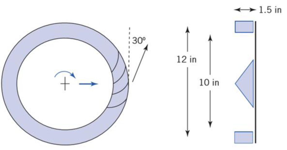
A blower has a rotor with 12-in. outside diameter and 10-in. inside diameter with 1,5-in high rotor blades. The flow rate through the blower is 500 ft3/min at a rotor speed of 1800 rpm. The air at blade inlet is in the radial direction and the discharge angle is 30° from the tangential direction. Determine the power required by the blower motor.
Expert Solution & Answer
Want to see the full answer?
Check out a sample textbook solution
Students have asked these similar questions
Quiz/An eccentrically loaded bracket is welded to the support as shown in Figure below. The load is static. The weld size
for weld w1 is h1=6mm, for w2 h2 5mm, and for w3 is h3 -5.5 mm. Determine the safety factor (S.f) for the welds.
F=22 kN. Use an AWS Electrode type (E90xx).
140
101.15
REDMI NOTE 8 PRO
AI QUAD CAMERA
F
(read image)
Problem 3.30
A piston-cylinder device contains 0.85 kg of refrigerant- 134a at -10°C. The piston that is free to move has a mass of 12 kg and a diameter of 25 cm. The local atmospheric pressure is 100 kPa. Now, heat is transferred to refrigerant-134a until the temperature is 15°C. Determine (a) the final pressure, (b) the change in the volume of the refrigerant, and (c) the change in the enthalpy of the refrigerant-134a.
please show Al work step by step
Chapter 10 Solutions
Fox And Mcdonald's Introduction To Fluid Mechanics
Ch. 10 - The geometry of a centrifugal water pump is r1 =...Ch. 10 - Find the resulting -groups when (a) D, , and Q or...Ch. 10 - Consider the centrifugal pump impeller dimensions...Ch. 10 - Dimensions of a centrifugal pump impeller areCh. 10 - Dimensions of a centrifugal pump impeller areCh. 10 - The blade is one of a series. Calculate the force...Ch. 10 - This blade is one of a series. What force is...Ch. 10 - A centrifugal water pump, with 15-cm-diameter...Ch. 10 - A centrifugal water pump designed to operate at...Ch. 10 - A series of blades, such as in Example 10.13,...
Ch. 10 - In passing through this blade system, the absolute...Ch. 10 - A centrifugal pump runs at 1750 rpm while pumping...Ch. 10 - A centrifugal water pump designed to operate at...Ch. 10 - Kerosene is pumped by a centrifugal pump. When the...Ch. 10 - In the water pump of Problem 10.8, the pump casing...Ch. 10 - Use data from Appendix C to choose points from the...Ch. 10 - Data from tests of a water suction pump operated...Ch. 10 - A centrifugal pump impeller having r1 = 50 mm, r2...Ch. 10 - A centrifugal pump impeller having dimensions and...Ch. 10 - An axial-flow fan operates in sea-level air at...Ch. 10 - Data measured during tests of a centrifugal pump...Ch. 10 - A small centrifugal pump, when tested at N = 2875...Ch. 10 - If the impeller of Problem 10.20 rotates between...Ch. 10 - At the outlet of a pump impeller of diameter 0.6 m...Ch. 10 - Typical performance curves for a centrifugal pump,...Ch. 10 - A pump with D = 500 mm delivers Q = 0.725 m3/s of...Ch. 10 - At its best efficiency point ( = 0.87), a...Ch. 10 - Using the performance curves in Appendix C, select...Ch. 10 - A pumping system must be specified for a lift...Ch. 10 - A centrifugal water pump operates at 1750 rpm; the...Ch. 10 - A set of eight 30-kW motor-pump units is used to...Ch. 10 - A blower has a rotor with 12-in. outside diameter...Ch. 10 - A centrifugal water pump has an impeller with an...Ch. 10 - Appendix C contains area bound curves for pump...Ch. 10 - Use data from Appendix C to verify the similarity...Ch. 10 - A centrifugal water pump has an impeller with...Ch. 10 - Catalog data for a centrifugal water pump at...Ch. 10 - A 1/3 scale model of a centrifugal water pump...Ch. 10 - Sometimes the variation of water viscosity with...Ch. 10 - A large deep fryer at a snack-food plant contains...Ch. 10 - Data from tests of a pump, with a...Ch. 10 - A four-stage boiler feed pump has suction and...Ch. 10 - A centrifugal pump operating at N = 2265 rpm lifts...Ch. 10 - A centrifugal pump is installed in a piping system...Ch. 10 - Part of the water supply for the South Rim of...Ch. 10 - Consider the flow system shown in Problem 8.94....Ch. 10 - Afire nozzle is supplied through 300 ft of...Ch. 10 - Performance data for a centrifugal fan of 3-ft...Ch. 10 - The performance data of Problem 10.57 are for a...Ch. 10 - Experimental test data for an aircraft engine fuel...Ch. 10 - Preliminary calculations for a hydroelectric power...Ch. 10 - Conditions at the inlet to the nozzle of a Pelton...Ch. 10 - A Francis turbine is to operate under a head of 46...Ch. 10 - A Kaplan (propeller with variable-pitch blades)...Ch. 10 - Francis turbine Units 19, 20, and 21, installed at...Ch. 10 - Measured data for performance of the reaction...Ch. 10 - For a flow rate of 12 L/s and turbine speed of 65...Ch. 10 - The velocity of the water jet driving this impulse...Ch. 10 - An impulse turbine is to develop 15 MW from a...Ch. 10 - An impulse turbine under a net head of 33 ft was...Ch. 10 - The absolute velocities and directions of the jets...Ch. 10 - A fanboat in the Florida Everglades is powered by...Ch. 10 - A jet-propelled aircraft traveling at 225 m/s...Ch. 10 - When an air jet of 1-in.-diameter strikes a series...Ch. 10 - The volume flow rate through the propeller of an...Ch. 10 - A typical American multi blade farm windmill has D...Ch. 10 - An airplane flies at 200 km/h through still air of...Ch. 10 - This ducted propeller unit drives a ship through...Ch. 10 - A model of an American multi blade farm windmill...Ch. 10 - A large Darrieus vertical axis wind turbine was...Ch. 10 - Show that this ducted propeller system when moving...Ch. 10 - This ducted propeller unit (now operating as a...Ch. 10 - What is the maximum power that can be expected...Ch. 10 - If an ideal windmill is operating at best...Ch. 10 - A prototype air compressor with a compression...Ch. 10 - Prob. 89PCh. 10 - We have seen many examples in Chapter 7 of...
Additional Engineering Textbook Solutions
Find more solutions based on key concepts
Describe some design trade-offs between efficiency and safety in some language you know.
Concepts Of Programming Languages
Comprehension Check 8-17
A motor with a power of 100 watts [W] is connected to a flywheel. How long, in units o...
Thinking Like an Engineer: An Active Learning Approach (4th Edition)
Distinguish among data definition commands, data manipulation commands, and data control commands.
Modern Database Management
Describe a method that can be used to gather a piece of data such as the users age.
Web Development and Design Foundations with HTML5 (8th Edition)
What are the advantages and disadvantages of a four-jaw independent chuck versus a three-jaw chuck?
Degarmo's Materials And Processes In Manufacturing
In Exercises 1 through 52, determine the output produced by the lines of code. DimdtAsDate=1/2/2020MessageBox.S...
Introduction To Programming Using Visual Basic (11th Edition)
Knowledge Booster


Learn more about
Need a deep-dive on the concept behind this application? Look no further. Learn more about this topic, mechanical-engineering and related others by exploring similar questions and additional content below.Similar questions
- Part 1 The storage tank contains lubricating oil of specific gravity 0.86 In one inclined side of the tank, there is a 0.48 m diameter circular inspection door, mounted on a horizontal shaft along the centre line of the gate. The oil level in the tank rests 8.8 m above the mounted shaft. (Please refer table 01 for relevant SG, D and h values). Describe the hydrostatic force and centre of pressure with the aid of a free body diagram of the inspection door. Calculate the magnitude of the hydrostatic force and locate the centre of pressure. 45° Estimate the moment that would have to be applied to the shaft to open the gate. Stop B If the oil level raised by 2 m from the current level, calculate the new moment required to open the gate. Figure 01arrow_forwardFrom thermodynamics please fill in the table show all work step by steparrow_forwardThe 150-lb skater passes point A with a speed of 6 ft/s. (Figure 1) Determine his speed when he reaches point B. Neglect friction. Determine the normal force exerted on him by the track at this point. 25 ft B = 4x A 20 ft xarrow_forward
- A virtual experiment is designed to determine the effect of friction on the timing and speed of packages being delivered to a conveyor belt and the normal force applied to the tube. A package is held and then let go at the edge of a circular shaped tube of radius R = 5m. The particle at the bottom will transfer to the conveyor belt, as shown below. Run the simulations for μ = 0, 0.1, 0.2, 0.3, 0.4, 0.5, 0.6 and determine the time and speed at which the package is delivered to the conveyor belt. In addition, determine the maximum normal force and its location along the path as measured by angle 0. Submit in hardcopy form: (0) Free Body Diagram, equations underneath, derivations (a) Your MATLAB mfile (b) A table listing the values in 5 columns: μ, T (time of transfer), V (speed of transfer), 0 (angle of max N), Nmax (max N) (c) Based on your results, explain in one sentence what you think will happen to the package if the friction is increased even further, e.g. μ = 0.8. NOTE: The ODE is…arrow_forwardPatm = 1 bar Piston m = 50 kg 5 g of Air T₁ = 600 K P₁ = 3 bar Stops A 9.75 x 10⁻³ m² FIGURE P3.88arrow_forwardAssume a Space Launch System (Figure 1(a)) that is approximated as a cantilever undamped single degree of freedom (SDOF) system with a mass at its free end (Figure 1(b)). The cantilever is assumed to be massless. Assume a wind load that is approximated with a concentrated harmonic forcing function p(t) = posin(ωt) acting on the mass. The known properties of the SDOF and the applied forcing function are given below. • Mass of SDOF: m =120 kip/g • Acceleration of gravity: g = 386 in/sec2 • Bending sectional stiffness of SDOF: EI = 1015 lbf×in2 • Height of SDOF: h = 2000 inches • Amplitude of forcing function: po = 6 kip • Forcing frequency: f = 8 Harrow_forward
- Assume a Space Launch System (Figure 1(a)) that is approximated as a cantilever undamped single degree of freedom (SDOF) system with a mass at its free end (Figure 1(b)). The cantilever is assumed to be massless. Assume a wind load that is approximated with a concentrated harmonic forcing function p(t) = posin(ωt) acting on the mass. The known properties of the SDOF and the applied forcing function are given below. • Mass of SDOF: m =120 kip/g • Acceleration of gravity: g = 386 in/sec2 • Bending sectional stiffness of SDOF: EI = 1015 lbf×in2 • Height of SDOF: h = 2000 inches • Amplitude of forcing function: po = 6 kip • Forcing frequency: f = 8 Hz Figure 1: Single-degree-of-freedom system in Problem 1. Please compute the following considering the steady-state response of the SDOF system. Do not consider the transient response unless it is explicitly stated in the question. (a) The natural circular frequency and the natural period of the SDOF. (10 points) (b) The maximum displacement of…arrow_forwardAssume a Space Launch System (Figure 1(a)) that is approximated as a cantilever undamped single degree of freedom (SDOF) system with a mass at its free end (Figure 1(b)). The cantilever is assumed to be massless. Assume a wind load that is approximated with a concentrated harmonic forcing function p(t) = posin(ωt) acting on the mass. The known properties of the SDOF and the applied forcing function are given below. • Mass of SDOF: m =120 kip/g • Acceleration of gravity: g = 386 in/sec2 • Bending sectional stiffness of SDOF: EI = 1015 lbf×in2 • Height of SDOF: h = 2000 inches • Amplitude of forcing function: po = 6 kip • Forcing frequency: f = 8 Hz Figure 1: Single-degree-of-freedom system in Problem 1. Please compute the following considering the steady-state response of the SDOF system. Do not consider the transient response unless it is explicitly stated in the question. (a) The natural circular frequency and the natural period of the SDOF. (10 points) (b) The maximum displacement of…arrow_forwardPlease solve 13 * √(2675.16)² + (63.72 + 2255,03)² = 175x106 can you explain the process for getting d seperate thank youarrow_forward
- If the 300-kg drum has a center of mass at point G, determine the horizontal and vertical components of force acting at pin A and the reactions on the smooth pads C and D. The grip at B on member DAB resists both horizontal and vertical components of force at the rim of the drum. P 60 mm; 60 mm: 600 mm A E 30° B C 390 mm 100 mm D Garrow_forwardThe design of the gear-and-shaft system shown requires that steel shafts of the same diameter be used for both AB and CD. It is further required that the angle D through which end D of shaft CD rotates not exceed 1.5°. Knowing that G = 77.2 GPa, determine the required diameter of the shafts. 40 mm 400 mm 100 mm 600 mm T-1000 N-m Darrow_forwardAssume a Space Launch System (Figure 1(a)) that is approximated as a cantilever undamped single degree of freedom (SDOF) system with a mass at its free end (Figure 1(b)). The cantilever is assumed to be massless. Assume a wind load that is approximated with a concentrated harmonic forcing function p(t) = posin(ωt) acting on the mass. The known properties of the SDOF and the applied forcing function are given below. • Mass of SDOF: m =120 kip/g • Acceleration of gravity: g = 386 in/sec2 • Bending sectional stiffness of SDOF: EI = 1015 lbf×in2 • Height of SDOF: h = 2000 inches • Amplitude of forcing function: po = 6 kip • Forcing frequency: f = 8 Hzarrow_forward
arrow_back_ios
SEE MORE QUESTIONS
arrow_forward_ios
Recommended textbooks for you
 Elements Of ElectromagneticsMechanical EngineeringISBN:9780190698614Author:Sadiku, Matthew N. O.Publisher:Oxford University Press
 Mechanics of Materials (10th Edition)Mechanical EngineeringISBN:9780134319650Author:Russell C. HibbelerPublisher:PEARSON
 Thermodynamics: An Engineering ApproachMechanical EngineeringISBN:9781259822674Author:Yunus A. Cengel Dr., Michael A. BolesPublisher:McGraw-Hill Education
 Control Systems EngineeringMechanical EngineeringISBN:9781118170519Author:Norman S. NisePublisher:WILEY
 Mechanics of Materials (MindTap Course List)Mechanical EngineeringISBN:9781337093347Author:Barry J. Goodno, James M. GerePublisher:Cengage Learning
 Engineering Mechanics: StaticsMechanical EngineeringISBN:9781118807330Author:James L. Meriam, L. G. Kraige, J. N. BoltonPublisher:WILEY
Elements Of Electromagnetics
Mechanical Engineering
ISBN:9780190698614
Author:Sadiku, Matthew N. O.
Publisher:Oxford University Press
Mechanics of Materials (10th Edition)
Mechanical Engineering
ISBN:9780134319650
Author:Russell C. Hibbeler
Publisher:PEARSON
Thermodynamics: An Engineering Approach
Mechanical Engineering
ISBN:9781259822674
Author:Yunus A. Cengel Dr., Michael A. Boles
Publisher:McGraw-Hill Education
Control Systems Engineering
Mechanical Engineering
ISBN:9781118170519
Author:Norman S. Nise
Publisher:WILEY
Mechanics of Materials (MindTap Course List)
Mechanical Engineering
ISBN:9781337093347
Author:Barry J. Goodno, James M. Gere
Publisher:Cengage Learning
Engineering Mechanics: Statics
Mechanical Engineering
ISBN:9781118807330
Author:James L. Meriam, L. G. Kraige, J. N. Bolton
Publisher:WILEY
Fluid Mechanics - Viscosity and Shear Strain Rate in 9 Minutes!; Author: Less Boring Lectures;https://www.youtube.com/watch?v=_0aaRDAdPTY;License: Standard youtube license