
Videos
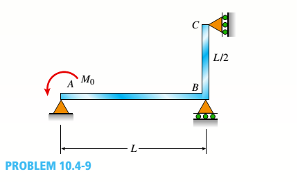
The continuous frame ABC has a pin support at A, roller supports at B and C and a rigid corner connection at B (see figure). Members AB and BC each have flexural rigidity EI. A moment Müacts counterclockwise at A. Note: Disregard axial deformations in member AB and consider only the effects of bending.
- Find all reactions of the frame.
Find the required new length of member AB in terms of L, so that
(a)
All the reactions of the frame.
Answer to Problem 10.4.9P
The reactions are :
Explanation of Solution
Given Information:
The following figure is given with all relevant information,

Calculation:
Consider the following free body diagram,
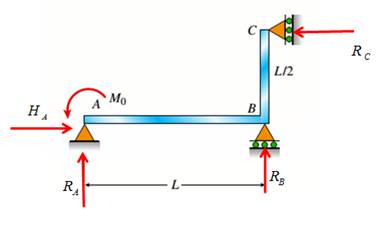
Take equilibrium of horizontal forces as,
Take equilibrium of vertical forces as,
Take equilibrium of moments about B as,
The bending moment at distance x from A along AB in part AB is given by,
Use second order deflection differential equation,
Integrate above equation to get rotation as,
Integrate above equation to get rotation as,
The bending moment at distance x from B along BC in part BC is given by,
Use second order deflection differential equation,
Integrate above equation to get rotation as,
Integrate above equation to get rotation as,
The constraint equations are,
Solve equations (1-8) to get integration constants and reactions.
So the reactions are
Conclusion:
Therefore, the reactions are:
(b)
Rotations at joints A, B, and C.
Answer to Problem 10.4.9P
Rotations at joints A, B, and C are
Explanation of Solution
Given Information:
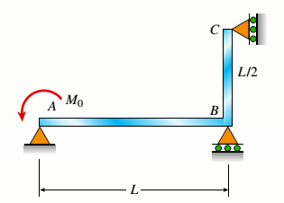
The following figure is given with all relevant information,

Calculation:
Consider the following free body diagram,

Take equilibrium of horizontal forces as,
Take equilibrium of vertical forces as,
Take equilibrium of moments about B as,
The bending moment at distance x from A along AB in part AB is given by,
Use second order deflection differential equation,
Integrate above equation to get rotation as,
Integrate above equation to get rotation as,
The bending moment at distance x from B along BC in part BC is given by,
Use second order deflection differential equation,
Integrate above equation to get rotation as,
Integrate above equation to get rotation as,
The constraint equations are,
Solve equations (1-8) to get integration constants and reactions.
So the reactions are
Substitute the integration constants and reactions in expressions of rotations to get,
Conclusion:
Therefore, rotations at joints A, B, and C are
(c)
Length of AB.
Answer to Problem 10.4.9P
Length of AB is
Explanation of Solution
Given Information:
The following figure is given with all relevant information,
Also
Calculation:
Consider the following free body diagram,

Take equilibrium of horizontal forces as,
Take equilibrium of vertical forces as,
Take equilibrium of moments about B as,
The bending moment at distance x from A along AB in part AB is given by,
Use second order deflection differential equation,
Integrate above equation to get rotation as,
Integrate above equation to get rotation as,
The bending moment at distance x from B along BC in part BC is given by,
Use second order deflection differential equation,
Integrate above equation to get rotation as,
Integrate above equation to get rotation as,
The constraint equations are,
Solve equations (1-8) to get integration constants and reactions.
So the reactions are
Substitute the integration constants and reactions in expressions of rotations to get,
Solve above equation to get
Conclusion:
Therefore, length of AB is
Want to see more full solutions like this?
Chapter 10 Solutions
Mechanics of Materials, SI Edition


- An elastic bar of length L spins with angular velocity ω about an axis, as shown in the figure below. The radial acceleration at a generic point x along the bar is a(x) = ω 2 x. Due to this radial acceleration, the bar stretches along x with displacement function u(x). The displacement u(x) is governed by the following equations: ( d dx (σ(x)) + ρa(x) = 0 PDE σ(x) = E du dx Hooke’s law (1) where σ(x) is the axial stress in the rod, ρ is the mass density, and E is the (constant) Young’s modulus. The bar is pinned on the rotation axis at x = 0, and it is free at x = L. Determine:1. Appropriate BCs for this physical problem.2. The displacement function u(x).3. The stress function σ(x).arrow_forwardWith reference to the given figure: a) Draw a free-body diagram of the structure supporting the pulley. b) Draw shear and bending moment diagrams for both the vertical and horizontal portions of the structure. 48 in. 100 lb 12 in. Cable 27 in. 12-in. pulley radius 100 lb Cablearrow_forwardConsider a standard piston engine . Draw a free body diagram of the piston. Then:a) For an A SI engine with a 100 mm bore at an instantaneous cylinder pressure of 42 bar i. Calculate the level of the combustion gas loading force on the wrist pin in kN. b) Repeat this calculationfor a forced-induction Diesel engine with a 145 mm boreat a cylinder pressure of 115 bararrow_forward
- A punch press with flywheel adequate to minimize speed fluctuation produces 120 punching strokes per minute, each providing an average force of 2000 N over a stroke of 50 mm. The press is driven through a gear reducer by a shaft rotating 200 rpm. Overall efficiency is 80%. a) What power (W) is transmitted through the shaft? b) What average torque is applied to the shaft?arrow_forward1.58 The crankshaft of a single-cylinder air compressor rotates 1800 rpm. The piston area is 2000 mm2 and the piston stroke is 50 mm. Assume a simple “idealized” case where the average gas pressure acting on the piston during the compression stroke is 1 MPa, and pressure during the intake stroke is negligible. The compressor is 80% efficient. A flywheel provides adequate control of the speed fluctuation. a) What motor power (kW) is required to drive the crankshaft? b) What torque is transmitted through the crankshaft?arrow_forward28. The shaft shown in Figure P5-28 is supported by bear- ings at each end, which have bores of 20.0 mm. Design the shaft to carry the given load if it is steady and the shaft is stationary. Make the dimension a as large as pos- sible while keeping the stress safe. Determine the required d 20 mm 5.4 kN d D = ? Length not to scale -α = = -125 mm 20 mm a = -250 mm- FIGURE P5-28 (Problems 28, 29, and 30)arrow_forward
- The motor shown operates at constant speed and develops a torque of 100 lb-in during normal operation. Attached to the motor shaft is a gear reducer of ratio 5:1, that is, the reducer output shaft rotates in the same direction as the motor but at one-fifth motor speed. Rotation of the reducer housing is prevented by the "torque arm" pin-connected at each end as shown. The reducer output shaft drives the load through a flexible coupling. Neglecting gravity and friction, what loads are applied to (a) the torque arm, (b) the motor output shaft, and (c) the reducer output shaft? Motor Gear reducer Flexible coupling (To load) Torque arm- Torque arm Reducer output shaft Motor Reducer Shaft rotationarrow_forwardPlease can you help with ten attatched question?arrow_forwardAn AISI 1018 steel ball with 1.100-in diameter is used as a roller between a flat plate made from 2024 T3 aluminum and a flat table surface made from ASTM No. 30 gray cast iron. Determine the maximum amount of weight that can be stacked on the aluminum plate without exceeding a maximum shear stress of 19.00 kpsi in any of the three pieces. Assume the figure given below, which is based on a typical Poisson's ratio of 0.3, is applicable to estimate the depth at which the maximum shear stress occurs for these materials. 1.0 0.8 Ratio of stress to Pmax 0.4 90 0.6 στ Tmax 0.2 0.5a a 1.5a 2a 2.5a За Distance from contact surface The maximum amount of weight that can be stacked on the aluminum plate is lbf.arrow_forward
- A carbon steel ball with 27.00-mm diameter is pressed together with an aluminum ball with a 36.00-mm diameter by a force of 11.00 N. Determine the maximum shear stress and the depth at which it will occur for the aluminum ball. Assume the figure given below, which is based on a typical Poisson's ratio of 0.3, is applicable to estimate the depth at which the maximum shear stress occurs for these materials. 1.0 0.8 Ratio of stress to Pma 9 0.6 στ 24 0.4 Tmax 0.2 0 0.5a a 1.5a Z 2a 2.5a За Distance from contact surface The maximum shear stress is determined to be MPa. The depth in the aluminum ball at which the maximum shear stress will occur is determined to be [ mm.arrow_forwardShow all work pleasearrow_forwardDraw top, side, front view With pen(cil) and paper Multi view drawing and handwriting all of itarrow_forward
 Mechanics of Materials (MindTap Course List)Mechanical EngineeringISBN:9781337093347Author:Barry J. Goodno, James M. GerePublisher:Cengage Learning