
Mechanics of Materials, SI Edition
9th Edition
ISBN: 9781337093354
Author: Barry J. Goodno, James M. Gere
Publisher: Cengage Learning
expand_more
expand_more
format_list_bulleted
Concept explainers
Videos
Textbook Question
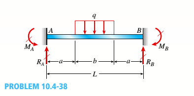
Chapter 10, Problem 10.4.38P
A fixed-end beam AB of a length L is subjected to a uniform load of intensity q acting over the middle region of the beam (sec figure).
- Obtain a formula for the fixed-end moments MAand MBin terms of the load q, the length L, and the length h of the loaded part of the beam.
with the ratio b/L varying between its extreme values of 0 and 1.
(c) For the special case in which ù = h = L/3, draw the shear-force and bending-moment diagrams for the beam, labeling all critical ordinates.
Expert Solution & Answer

Trending nowThis is a popular solution!

Students have asked these similar questions
(read image)
(read image)
(read me)
Chapter 10 Solutions
Mechanics of Materials, SI Edition
Ch. 10 - A propped cantilever steel beam is constructed...Ch. 10 - A fixed-end b earn is subjected to a point load at...Ch. 10 - A propped cantilever beam AB of a length L is...Ch. 10 - A fixed-end beam AB of a length L supports a...Ch. 10 - A cantilever beam AB of a length L has a fixed...Ch. 10 - A cantilever beam of a length L and loaded by a...Ch. 10 - A cantilever beam has a length L and is loaded by...Ch. 10 - A propped cantilever beam of a length L is loaded...Ch. 10 - A propped cantilever beam of a length L is loaded...Ch. 10 - A fixed-end beam of a length L is loaded by a...
Ch. 10 - A fixed-end b earn of a length L is loaded by a...Ch. 10 - A fixed-end beam of a length L is loaded by...Ch. 10 - A counterclockwise moment M0acts at the midpoint...Ch. 10 - A propped cantilever beam of a length L is loaded...Ch. 10 - A propped cantilever beam is subjected to uniform...Ch. 10 - Repeat Problem 10.3-15 using L = 3.5 m, max = 3...Ch. 10 - A two-span, continuous wood girder (E = 1700 ksi)...Ch. 10 - A fixed-end beam AB carries point load P acting at...Ch. 10 - A fixed-end beam AB supports a uniform load of...Ch. 10 - -4-4 A cantilever beam is supported at B by cable...Ch. 10 - A propped cantilever beam AB of a length L carries...Ch. 10 - A beam with a sliding support at B is loaded by a...Ch. 10 - A propped cantilever beam of a length 2L with a...Ch. 10 - The continuous frame ABC has a pin support at /l,...Ch. 10 - The continuous frame ABC has a pin support at A,...Ch. 10 - Beam AB has a pin support at A and a roller...Ch. 10 - The continuous frame ABCD has a pin support at B:...Ch. 10 - Two flat beams AB and CD, lying in horizontal...Ch. 10 - -4-13 A propped cantilever beam of a length 2L is...Ch. 10 - A propped cantilever beam of a length 2L is loaded...Ch. 10 - Determine the fixed-end moments (MAand MB) and...Ch. 10 - A continuous beam ABC wit h two unequal spans, one...Ch. 10 - Beam ABC is fixed at support A and rests (at point...Ch. 10 - A propped cantilever beam has flexural rigidity EI...Ch. 10 - A triangularly distributed 1oad with a maximum...Ch. 10 - A fixed-end beam is loaded by a uniform load q =...Ch. 10 - Uniform load q = 10 lb/ft acts over part of the...Ch. 10 - A propped cantilever beam with a length L = 4 m is...Ch. 10 - A cant i levé r b ea m i s supported by a tie rod...Ch. 10 - The figure shows a nonprismatic, propped...Ch. 10 - A beam ABC is fixed at end A and supported by beam...Ch. 10 - A three-span continuous beam A BCD with three...Ch. 10 - A beam rests on supports at A and B and is loaded...Ch. 10 - A propped cantilever beam is subjected to two...Ch. 10 - A propped cantilever beam is loaded by a...Ch. 10 - A fixed-end beam AB of a length L is subjected to...Ch. 10 - A temporary wood flume serving as a channel for...Ch. 10 - Two identical, simply supported beams AB and CD...Ch. 10 - The cantilever beam AB shown in the figure is an...Ch. 10 - The beam AB shown in the figure is simply...Ch. 10 - The continuous frame ABC has a fixed support at A,...Ch. 10 - The continuous frame ABC has a pinned support at...Ch. 10 - A wide-flange beam ABC rests on three identical...Ch. 10 - A fixed-end beam AB of a length L is subjected to...Ch. 10 - A beam supporting a uniform load of intensity q...Ch. 10 - A thin steel beam AB used in conjunction with an...Ch. 10 - Find an expression for required moment MA(in terms...Ch. 10 - Repeat Problem 10.4-41 for the loading shown in...Ch. 10 - A propped cantilever beam is loaded by two...Ch. 10 - A cable CD of a length H is attached to the third...Ch. 10 - A propped cantilever beam, fixed at the left-hand...Ch. 10 - Solve t he preceding problem by integrating the...Ch. 10 - A two-span beam with spans of lengths L and L/3 is...Ch. 10 - Solve the preceding problem by integrating the...Ch. 10 - Assume that the deflected shape of a beam AB with...Ch. 10 - (a) A simple beam AB with length L and height h...
Knowledge Booster


Learn more about
Need a deep-dive on the concept behind this application? Look no further. Learn more about this topic, mechanical-engineering and related others by exploring similar questions and additional content below.Similar questions
- (read me)arrow_forward(read image)arrow_forwardQu. 13 What are the indices for the Direction 2 indicated by vector in the following sketch? Qu. 14 Determine the indices for the direction A and B shown in the following cubic unit cell. please show all work step by step from material engineeringarrow_forward
- The thin-walled open cross section shown is transmitting torque 7. The angle of twist ₁ per unit length of each leg can be determined separately using the equation 01 = 3Ti GLIC 3 where G is the shear modulus, ₁ is the angle of twist per unit length, T is torque, and L is the length of the median line. In this case, i = 1, 2, 3, and T; represents the torque in leg i. Assuming that the angle of twist per unit length for each leg is the same, show that T= Lic³ and Tmaz = G01 Cmax Consider a steel section with Tallow = 12.40 kpsi. C1 2 mm L1 20 mm C2 3 mm L2 30 mm C3 2 mm L3 25 mm Determine the torque transmitted by each leg and the torque transmitted by the entire section. The torque transmitted by the first leg is | N-m. The torque transmitted by the second leg is N-m. The torque transmitted by the third leg is N-m. The torque transmitted by the entire section is N-m.arrow_forwardPlease help, make sure it's to box out and make it clear what answers go where...arrow_forwardThe cylinder floats in the water and oil to the level shown. Determine the weight of the cylinder. (rho)o=910 kg/m^3arrow_forward
arrow_back_ios
SEE MORE QUESTIONS
arrow_forward_ios
Recommended textbooks for you
 Mechanics of Materials (MindTap Course List)Mechanical EngineeringISBN:9781337093347Author:Barry J. Goodno, James M. GerePublisher:Cengage Learning
Mechanics of Materials (MindTap Course List)
Mechanical Engineering
ISBN:9781337093347
Author:Barry J. Goodno, James M. Gere
Publisher:Cengage Learning
Types Of loads - Engineering Mechanics | Abhishek Explained; Author: Prime Course;https://www.youtube.com/watch?v=4JVoL9wb5yM;License: Standard YouTube License, CC-BY