
Videos
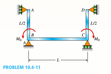
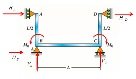
The continuous frame ABCD has a pin support at B: roller supports at A,C, and D; and rigid corner connections at B and C (see figure). Members AB, BC, and CD each have flexural rigidity EL Moment M0acts counterclockwise at B and clockwise at C. Note: Disregard axial deformations in member A Band consider only the effects of bending.
- Find all reactions of the frame.
Find joint rotations
(a)
All the reactions of the frame.
Answer to Problem 10.4.11P
The reactions are :
Explanation of Solution
Given Information:
The following figure is given with all relevant information,
Calculation:
Consider the following free body diagram,
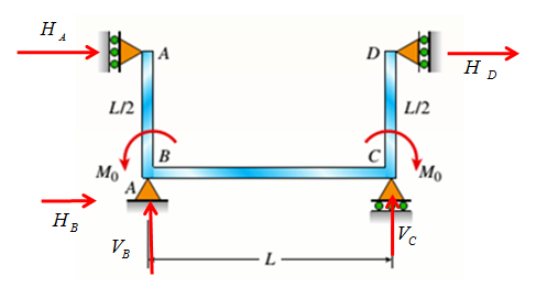
Take equilibrium of horizontal forces as,
Take equilibrium of vertical forces as,
Take equilibrium of moments about B as,
The bending moment at distance x from A along AB in part AB is given by,
Use second order deflection differential equation,
Integrate above equation to get rotation as,
Integrate above equation to get rotation as,
The bending moment at distance x from B along BC in part BC is given by,
Use second order deflection differential equation,
Integrate above equation to get rotation as,
Integrate above equation to get rotation as,
The bending moment at distance x from C along CD in part CD is given by,
Use second order deflection differential equation,
Integrate above equation to get rotation as,
Integrate above equation to get rotation as,
The constraint equations are,
Solve equations (1-10) to get integration constants and reactions.
So the reactions are
Conclusion:
Therefore, the reactions are:
(b)
Rotations at A, B, C and D.
Answer to Problem 10.4.11P
Rotations at A, B, C and D are
Explanation of Solution
Given Information:
The following figure is given with all relevant information,

Calculation:
Consider the following free body diagram,

Take equilibrium of horizontal forces as,
Take equilibrium of vertical forces as,
Take equilibrium of moments about B as,
The bending moment at distance x from A along AB in part AB is given by,
Use second order deflection differential equation,
Integrate above equation to get rotation as,
Integrate above equation to get rotation as,
The bending moment at distance x from B along BC in part BC is given by,
Use second order deflection differential equation,
Integrate above equation to get rotation as,
Integrate above equation to get rotation as,
The bending moment at distance x from C along CD in part CD is given by,
Use second order deflection differential equation,
Integrate above equation to get rotation as,
Integrate above equation to get rotation as,
The constraint equations are,
Solve equations (1-10) to get integration constants and reactions.
So the reactions are
Substitute reactions and integration constants in expression of rotation to get,
Conclusion:
Therefore, rotations at A, B, C and D are
(c)
Reactions and rotations at A, B, C and D.
Answer to Problem 10.4.11P
Reactions and rotations at A, B, C and D are
Explanation of Solution
Given Information:
The following figure is given with all relevant information,
Calculation:
Consider the following free body diagram,
Take equilibrium of horizontal forces as,
Take equilibrium of vertical forces as,
Take equilibrium of moments about B as,
The bending moment at distance x from A along AB in part AB is given by,
Use second order deflection differential equation,
Integrate above equation to get rotation as,
Integrate above equation to get rotation as,
The bending moment at distance x from B along BC in part BC is given by,
Use second order deflection differential equation,
Integrate above equation to get rotation as,
Integrate above equation to get rotation as,
The bending moment at distance x from C along CD in part CD is given by,
Use second order deflection differential equation,
Integrate above equation to get rotation as,
Integrate above equation to get rotation as,
The constraint equations are,
Solve equations (1-10) to get integration constants and reactions.
So the reactions are
Substitute reactions and integration constants in expression of rotation to get,
Conclusion:
Therefore, reactions and rotations at A, B, C and D are
Want to see more full solutions like this?
Chapter 10 Solutions
Mechanics of Materials, SI Edition


- In cold isostatic pressing, the mold is most typically made of which one of the following: thermosetting polymer tool steel sheet metal textile rubberarrow_forwardThe coefficient of friction between the part and the tool in cold working tends to be: lower higher no different relative to its value in hot workingarrow_forwardThe force F={25i−45j+15k}F={25i−45j+15k} lblb acts at the end A of the pipe assembly shown in (Figure 1). Determine the magnitude of the component F1 which acts along the member AB. Determine the magnitude of the component F2 which acts perpendicular to the AB.arrow_forward
 Mechanics of Materials (MindTap Course List)Mechanical EngineeringISBN:9781337093347Author:Barry J. Goodno, James M. GerePublisher:Cengage Learning