
Applied Statics and Strength of Materials (6th Edition)
6th Edition
ISBN: 9780133840544
Author: George F. Limbrunner, Craig D'Allaird, Leonard Spiegel
Publisher: PEARSON
expand_more
expand_more
format_list_bulleted
Concept explainers
Videos
Textbook Question
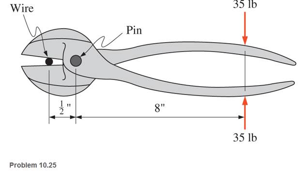
Chapter 10, Problem 10.25SP
A pair of wire cutters is designed to operate under a maximum 35 lb force applied, as shown. Determine the required diameter of the pin (to the next higher
Expert Solution & Answer
Want to see the full answer?
Check out a sample textbook solution
Students have asked these similar questions
12-217. The block B is sus-
pended from a cable that is at-
tached to the block at E, wraps
around three pulleys, and is tied to
the back of a truck. If the truck
starts from rest when ID is zero,
and moves forward with a constant
acceleration of ap = 0.5 m/s²,
determine the speed of the block at
D
the instant x = 2 m. Neglect
the size of the pulleys in the calcu-
lation. When xƊ = 0, yc = 5 m,
so that points C and D are at the
Prob. 12-217
5 m
yc
=2M
Xp
solve both and show matlab code
auto controls
12-82. The roller coaster car trav-
els down the helical path at con-
stant speed such that the paramet-
ric equations that define its posi-
tion are
x = c sin kt, y = c cos kt,
z = h - bt, where c, h, and b
are constants. Determine the mag-
nitudes of its velocity and accelera-
tion.
Prob. 12-82
N
Chapter 10 Solutions
Applied Statics and Strength of Materials (6th Edition)
Ch. 10 - A 916 - in. - diameter steel rod is tested in...Ch. 10 - A concrete cylinder 150 mm in diameter was tested...Ch. 10 - Prob. 10.3PCh. 10 - The data from the tension test of a steel specimen...Ch. 10 - An 18-in.-long titanium alloy rod is subjected to...Ch. 10 - ASTM A36 steel rods are used to support a balcony....Ch. 10 - A 450-mm-long AISI 1020 steel rod is subjected to...Ch. 10 - A tension member in a roof truss is composed of...Ch. 10 - A short, solid, compression member of circular...Ch. 10 - A main cable in a large bridge is designed for a...
Ch. 10 - Test results of a steel specimen indicated an...Ch. 10 - A concrete canoe in storage is supported by two...Ch. 10 - A load is applied to a rigid bar that is...Ch. 10 - Prob. 10.14CPCh. 10 - Write a program that will allow a user to input...Ch. 10 - A 12 - in. - diaiíct.cr structural nickel steel...Ch. 10 - Compute the modulus of elasticity of a copper...Ch. 10 - A concrete cylinder 6 in. in diameter was tested...Ch. 10 - An aluminum bar 2 in. by 12 - in. in cross section...Ch. 10 - During a tensile test of a steel specimen, the...Ch. 10 - A 12.5-mm-diameter steel rod was subjected to a...Ch. 10 - Prob. 10.22SPCh. 10 - A standard steel specimen having a diameter of...Ch. 10 - 10.24 A tension member in a structure is composed...Ch. 10 - A pair of wire cutters is designed to operate...Ch. 10 - Calculate the end bearing length required for a...Ch. 10 - Design a 3-m-long rod subjected to a tensile load...Ch. 10 - The collar bearing shown is subjected to a...Ch. 10 - A 10-ft-long steel member is subjected to a...Ch. 10 - Two steel bars A and B support a load P, as shown....Ch. 10 - Prob. 10.31SP
Knowledge Booster


Learn more about
Need a deep-dive on the concept behind this application? Look no further. Learn more about this topic, mechanical-engineering and related others by exploring similar questions and additional content below.Similar questions
- Given: = refueling Powertran SOURCE EMISSIONS vehide eff eff gasoline 266g co₂/kwh- HEV 0.90 0.285 FLgrid 411ilg Co₂/kWh 41111gCo₂/kWh EV 0.85 0.80 Production 11x10% og CO₂ 13.7 x 10°g CO₂ A) Calculate the breakeven pont (in km driven) for a EV against on HEV in Florida of 0.1kWh/kM Use a drive cycle conversion 5) How efficient would the powertrain of the HEV in this example have to be to break even with an EV in Florida after 150,000 Miles of service (240,000) km Is it plausible to achieve the answer from pert b Consideans the HaXINERY theoretical efficiency of the Carnot cycle is 5020 and there are additional losses of the transMISSION :- 90% efficiency ? c A what do you conclude is the leading factor in why EVs are less emissive than ICE,arrow_forwardsolve autocontrolsarrow_forwardProblem 3.21P: Air at 100F(38C) db,65F(18C) wb, and sea-level pressure is humidified adiabatically with steam. The steam supplied contains 20 percent moisture(quality of 0.80) at 14.7psia(101.3kpa). The air is humidified to 60 percent relative humidity. Find the dry bulb temperature of the humidified air using (a)chart 1a or 1b and (b) the program PSYCH.arrow_forward
- A pump delivering 230 lps of water at 30C has a 300-mm diameter suction pipe and a 254-mm diameter discharge pipe as shown in the figure. The suction pipe is 3.5 m long and the discharge pipe is 23 m long, both pipe's materials are cast iron. The water is delivered 16m above the intake water level. Considering head losses in fittings, valves, and major head loss. a) Find the total dynamic head which the pump must supply. b)It the pump mechanical efficiency is 68%, and the motor efficiency is 90%, determine the power rating of the motor in hp.given that: summation of K gate valve = 0.25check valve=390 degree elbow= 0.75foot valve= 0.78arrow_forwardA pump delivering 230 lps of water at 30C has a 300-mm diameter suction pipe and a 254-mm diameter discharge pipe as shown in the figure. The suction pipe is 3.5 m long and the discharge pipe is 23 m long, both pipe's materials are cast iron. The water is delivered 16m above the intake water level. Considering head losses in fittings, valves, and major head loss. a) Find the total dynamic head which the pump must supply. b)It the pump mechanical efficiency is 68%, and the motor efficiency is 90%, determine the power rating of the motor in hp.arrow_forwardThe tensile 0.2 percent offset yield strength of AISI 1137 cold-drawn steel bars up to 1 inch in diameter from 2 mills and 25 heats is reported as follows: Sy 93 95 101 f 97 99 107 109 111 19 25 38 17 12 10 5 4 103 105 4 2 where Sy is the class midpoint in kpsi and fis the number in each class. Presuming the distribution is normal, determine the yield strength exceeded by 99.0% of the population. The yield strength exceeded by 99.0% of the population is kpsi.arrow_forward
- Solve this problem and show all of the workarrow_forwardI tried to go through this problem but I don't know what I'm doing wrong can you help me?arrow_forwardGenerate the kinematic diagram of the following mechanisms using the given symbols. Then, draw their graphs and calculate their degrees of freedom (DoF) using Gruebler's formula. PUNTO 2. PUNTO 3. !!!arrow_forward
arrow_back_ios
SEE MORE QUESTIONS
arrow_forward_ios
Recommended textbooks for you
 Elements Of ElectromagneticsMechanical EngineeringISBN:9780190698614Author:Sadiku, Matthew N. O.Publisher:Oxford University Press
 Mechanics of Materials (10th Edition)Mechanical EngineeringISBN:9780134319650Author:Russell C. HibbelerPublisher:PEARSON
 Thermodynamics: An Engineering ApproachMechanical EngineeringISBN:9781259822674Author:Yunus A. Cengel Dr., Michael A. BolesPublisher:McGraw-Hill Education
 Control Systems EngineeringMechanical EngineeringISBN:9781118170519Author:Norman S. NisePublisher:WILEY
 Mechanics of Materials (MindTap Course List)Mechanical EngineeringISBN:9781337093347Author:Barry J. Goodno, James M. GerePublisher:Cengage Learning
 Engineering Mechanics: StaticsMechanical EngineeringISBN:9781118807330Author:James L. Meriam, L. G. Kraige, J. N. BoltonPublisher:WILEY
Elements Of Electromagnetics
Mechanical Engineering
ISBN:9780190698614
Author:Sadiku, Matthew N. O.
Publisher:Oxford University Press
Mechanics of Materials (10th Edition)
Mechanical Engineering
ISBN:9780134319650
Author:Russell C. Hibbeler
Publisher:PEARSON
Thermodynamics: An Engineering Approach
Mechanical Engineering
ISBN:9781259822674
Author:Yunus A. Cengel Dr., Michael A. Boles
Publisher:McGraw-Hill Education
Control Systems Engineering
Mechanical Engineering
ISBN:9781118170519
Author:Norman S. Nise
Publisher:WILEY
Mechanics of Materials (MindTap Course List)
Mechanical Engineering
ISBN:9781337093347
Author:Barry J. Goodno, James M. Gere
Publisher:Cengage Learning
Engineering Mechanics: Statics
Mechanical Engineering
ISBN:9781118807330
Author:James L. Meriam, L. G. Kraige, J. N. Bolton
Publisher:WILEY
Everything About COMBINED LOADING in 10 Minutes! Mechanics of Materials; Author: Less Boring Lectures;https://www.youtube.com/watch?v=N-PlI900hSg;License: Standard youtube license