
Concept explainers
Videos
Light Source Comparison A
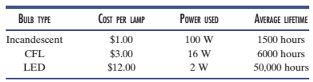
Today people have three competing light sources for home use. This problem asks you to determine the trade-offs between the costs of the three types of lights. In this example, all three emit the same amount of light (lumens). The following table shows the salient properties of each lamp. Over the lifetime of one light-emitting diode (LED) lamp, how much cost savings is there by using the LED lamp over the traditional incandescent bulb and over the compact fluorescent lamp (CFL) if electricity costs 10¢/kWh?
Want to see the full answer?
Check out a sample textbook solution
Chapter 1 Solutions
ANALYSIS+DESIGN OF LINEAR CIRCUITS(LL)
Additional Engineering Textbook Solutions
Modern Database Management
Java: An Introduction to Problem Solving and Programming (8th Edition)
Starting Out with C++: Early Objects (9th Edition)
Starting Out With Visual Basic (8th Edition)
Computer Science: An Overview (13th Edition) (What's New in Computer Science)
Degarmo's Materials And Processes In Manufacturing


- Use the ramp generator circuit in Fig. B2a to generate the waveform shown in Fig. B2b. Write four equations relating resistors R1, R2, R3, capacitor C and voltages Vs, VR and VA.to the waveform parameters T₁, T, Vcm and Vm- If R = R2 = R3, R₁ = 2R, C = 1 nF, Vcm = 2 V and Vm = 1 V, T₁ = 2 μs and T = 10 μs solve for the values of R, Vs, VR and VA using your equations from part a(i). VR C +VA R3 V₂ Vo мат R1 VsO+ V₁ R₂ Figure B2a Vout Vcm+Vm Vcm Vcm-Vm 0 T₁ T 2T time Figure B2barrow_forwardThe circuit in Figure B1a is a common analogue circuit block. Explain why you would need such a circuit. Draw another circuit in which you use the current flowing in this loop to bias a common source amplifier. This circuit is not ideal for standard CMOS technologies due to threshold shift. Why? Draw an improved version of this circuit to make it better. VDD (W)P MA M3. (), REF (쁜)~ M₁ M2 lout 시~ Rsarrow_forward23bcarrow_forward
- Draw the small-signal equivalent circuit of a single transistor amplifier given in figure B1b. Assume the current source to be ideal. Determine the Open-loop transfer function, pole frequency and gain-bandwidth product all in terms of transistor parameters 9m, To and CL. If the load capacitance is 1pF and the necessary unity gain frequency is 600MHz, find the gm for this transistor. V₁ V₁ CLarrow_forward23baarrow_forward23caarrow_forward
 Electricity for Refrigeration, Heating, and Air C...Mechanical EngineeringISBN:9781337399128Author:Russell E. SmithPublisher:Cengage Learning
 Delmar's Standard Textbook Of ElectricityElectrical EngineeringISBN:9781337900348Author:Stephen L. HermanPublisher:Cengage Learning