
ANALYSIS+DESIGN OF LINEAR CIRCUITS(LL)
8th Edition
ISBN: 9781119235385
Author: Thomas
Publisher: WILEY
expand_more
expand_more
format_list_bulleted
Videos
Textbook Question
Chapter 1, Problem 1.22P
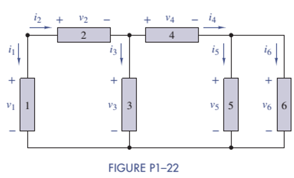
Figure P1-22 shows an electric circuit with a voltage and a current variable assigned to each of the six devices. The device voltages and currents are observed to be as follows: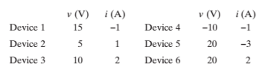
Find the power associated with each device and state whether the device is absorbing or delivering power. Use the power balance to check your work.
Expert Solution & Answer
Want to see the full answer?
Check out a sample textbook solution
Students have asked these similar questions
For the Circuit Below Find:
A) io in terms of Rb and the numerical resistor values provided in the schematic. Reduce your
solution to a minimal Equations
B)the power delivered across Rb in terms of Rb and the numerical resistor values provided in the
schematic. Reduce your solution to a minimal equation.
C) the power delivered across Rc if Rb is 5 Q
Ra $50
15Ω
M
120
90V
+1
Rb
150 150
m
Rc
Problems
A.1 The square-law modulator is a device for the generation of DSB-PC-AM signals. In the square-law modulator, the sum of the modulating signal and the carrier wave
forms the input signal to a nonlinear device. The output signal of the nonlinear device is a linear combination of the input signal and the square of the input signal. The
output signal of the nonlinear device is then band-pass filtered. The BPF has a center frequency that is the same as the carrier frequency and a bandwidth that is twice
the message bandwidth. Show the output of the BPF is a DSB-PC-AM signal, and determine a requirement between the carrier frequency and the message bandwidth
that must be satisfied.
Give the current voltage relationship of the D-MOSFET and E-MOSFET.
Chapter 1 Solutions
ANALYSIS+DESIGN OF LINEAR CIRCUITS(LL)
Ch. 1 - Given an electrical quantity described in terms of...Ch. 1 - Express the following quantities to the nearest...Ch. 1 - An ampere-hour (Ah) meter measures the time...Ch. 1 - Electric power companies measure energy...Ch. 1 - Fill in the blanks in the following statements. To...Ch. 1 - Which of the two entries is larger? 1000...Ch. 1 - A wire carries a constant current of 30A. How many...Ch. 1 - The net positive charge flowing through a device...Ch. 1 - Figure P1-9 shows a plot of the net positive...Ch. 1 - The net negative charge flowing through a device...
Ch. 1 - A cell phone charger outputs 9.6 V and is...Ch. 1 - For 0t5s, the current through a device is...Ch. 1 - The charge flowing through a device is...Ch. 1 - The 12-V automobile battery in Figure P1-14 has an...Ch. 1 - The current through a device is zero for t0 and is...Ch. 1 - A string of holiday lights is protected by a 12A...Ch. 1 - When illuminated the relationship for a photocell...Ch. 1 - A new 6-V alkaline lantern battery delivers...Ch. 1 - The maximum current allowed by a device's power...Ch. 1 - Traffic lights are being converted from...Ch. 1 - Two electrical devices are connected as shown in...Ch. 1 - Figure P1-22 shows an electric circuit with a...Ch. 1 - Figure P1-22 shows an electric circuit with a...Ch. 1 - In Figure P1-24 the voltage v2 is 10 V and v4 is 5...Ch. 1 - For t0, the voltage across and power absorbed by a...Ch. 1 - Repeat Problem 1-22 using MATLAB to perform the...Ch. 1 - Using the passive sign convention, the voltage...Ch. 1 - Power Ratio (PR) in dB A stereo amplifier takes...Ch. 1 - AC to DC Converter A manufacturer's data sheet for...Ch. 1 - Charge-Storage Device A capacitor is a...Ch. 1 - Compute Data Sheet A manufacturer's data sheet for...Ch. 1 - Light Source Comparison A Today people have three...
Additional Engineering Textbook Solutions
Find more solutions based on key concepts
7.13* For a bearing
DE = NUS 5 53’56 ”WT and angles to the right, compute the bearing of PG if angle
DEF 2 88°...
Elementary Surveying: An Introduction To Geomatics (15th Edition)
What different kinds of surfaces can be produced by turning versus facing?
Degarmo's Materials And Processes In Manufacturing
In Exercises 1 through 52, determine the output produced by the lines of code. DimdtlAsDate=2/1/20162016wasalea...
Introduction To Programming Using Visual Basic (11th Edition)
Suppose a person is typing forty words per minute at a keyboard. (A word is considered to be five characters.) ...
Computer Science: An Overview (13th Edition) (What's New in Computer Science)
Describe two properties that each candidate key must satisfy.
Modern Database Management
Today, CPUs are small chips known as ____. a. ENIACs b. microprocessors c. memory chips d. operating systems
Starting Out with Programming Logic and Design (5th Edition) (What's New in Computer Science)
Knowledge Booster


Learn more about
Need a deep-dive on the concept behind this application? Look no further. Learn more about this topic, electrical-engineering and related others by exploring similar questions and additional content below.Similar questions
- Answer A is wrong.arrow_forwardThe part of machine level instruction, which tells the central processor what was to be done is: A. Address B. None of the above C. Operation code D. Operandarrow_forwardWhich of the following statement is TRUE? 1. In RISC processors, each instruction requires only two clock cycles to complete, resulting in consistent execution time 2. RISC has more transistors and fewer registers 3. RISC has more registers and fewer transistorsarrow_forward
- A half-wave controlled rectifier is supplied by a 230 Vrms voltage source and has load resistance of 2502. Calculate the delay angle a that produces a load-absorbed power of 200W.arrow_forwardnot use ai pleasearrow_forwardFigure 1 shows a half-wave controlled rectifier which is supplied by a Vin = 120 Vrms voltage source. Assume that the load resistance is R = 10 2. Determine: a) The firing angle a of the thyristor to produce an average output voltage 50Vdc. Vin=Vmsinoot b) The average power Po absorbed by the load R. Figure 1 R = 1092arrow_forward
- Q1. What is power dissipation in the Zener diode circuit given for a) RL=100 Ohm ? b) RL=∞arrow_forwardThe one-line diagram of an unloaded power system is shown below. Reactances of the two sections of transmission line are shown on the diagram. The generators and transformers are rated as follows: 20 MVA, 13.8 kV, X = 0.20 p.u Generator 1: Generator 2: Generator 3: 30 MVA, 18 kV, X = 0.20 p.u Transformer Ti: Transformer T2: 30 MVA, 20 kV, X = 0.20 p.u 25 MVA, 220Y/13.8A kV, X = 10% Three single-phase units each rated 10 MVA, 127/18 kV, X = 10% HT sides connected in wye Transformer T3: LT sides connected in delta 35 MVA, 220Y/22Y KV, X = 10% j80 Q j100 Q Line 1 Line 2 T₁ T₂ Draw the impedance diagram with all reactances marked in per unit. Choose a base of 50 MVA, 13.8 kV in the circuit of generator 1.arrow_forwardntotnarrow_forward
arrow_back_ios
SEE MORE QUESTIONS
arrow_forward_ios
Recommended textbooks for you
 Delmar's Standard Textbook Of ElectricityElectrical EngineeringISBN:9781337900348Author:Stephen L. HermanPublisher:Cengage Learning
Delmar's Standard Textbook Of Electricity
Electrical Engineering
ISBN:9781337900348
Author:Stephen L. Herman
Publisher:Cengage Learning
Lesson 2 - Source Transformations, Part 2 (Engineering Circuits); Author: Math and Science;https://www.youtube.com/watch?v=7gno74RhVGQ;License: Standard Youtube License