
Mechanics of Materials, 7th Edition
7th Edition
ISBN: 9780073398235
Author: Ferdinand P. Beer, E. Russell Johnston Jr., John T. DeWolf, David F. Mazurek
Publisher: McGraw-Hill Education
expand_more
expand_more
format_list_bulleted
Concept explainers
Videos
Textbook Question
Chapter 9.5, Problem 101P
For the cantilever beam and loading shown, determine (a) the lope at point C, (b) the deflection at point C. Use E = 29 × 106 psi.
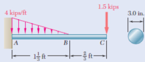
Fig. P9.101
Expert Solution & Answer
Want to see the full answer?
Check out a sample textbook solution
Students have asked these similar questions
using the theorem of three moments, find all the moments, I need concise calculations only
Practise question need help on
Can you show explaination and working. The answer from the text book is Q=5.03 X 10^-3
Chapter 9 Solutions
Mechanics of Materials, 7th Edition
Ch. 9.2 - In the following problems assume that the flexural...Ch. 9.2 - In the following problems assume that the flexural...Ch. 9.2 - In the following problems assume that the flexural...Ch. 9.2 - 9.1 through 9.4 For the loading shown, determine...Ch. 9.2 - 9.5 and 9.6 For the cantilever beam and loading...Ch. 9.2 - 9.5 and 9.6 For the cantilever beam and loading...Ch. 9.2 - For the beam and loading shown, determine (a) the...Ch. 9.2 - For the beam and loading shown, determine (a) the...Ch. 9.2 - Knowing that beam .AB is a W10 33 rolled shape...Ch. 9.2 - Knowing that beam AB is an S200 34 roiled shape...
Ch. 9.2 - For the beam and loading shown, (a) express the...Ch. 9.2 - (a) Determine the location and magnitude of the...Ch. 9.2 - For the beam and loading shown, determine the...Ch. 9.2 - Knowing that beam AE is a W360 101 rolled shape...Ch. 9.2 - For the beam and loading shown, knowing that a = 2...Ch. 9.2 - Knowing that beam AE is an S200 27.4 rolled shape...Ch. 9.2 - For the beam and loading shown, determine (a) the...Ch. 9.2 - For the beam and loading shown, determine (a) the...Ch. 9.2 - 9.19 through 9.22 For the beam and loading shown,...Ch. 9.2 - 9.19 through 9.22 For the beam and loading shown,...Ch. 9.2 - 9.19 through 9.22 For the beam and loading shown,...Ch. 9.2 - 9.19 through 9.22 For the beam and loading shown,...Ch. 9.2 - For the beam shown, determine the reaction at the...Ch. 9.2 - For the beam shown, determine the reaction at the...Ch. 9.2 - 9.25 through 9.28 Determine the reaction at the...Ch. 9.2 - 9.25 through 9.28 Determine the reaction at the...Ch. 9.2 - Prob. 27PCh. 9.2 - 9.25 through 9.28 Determine the reaction at the...Ch. 9.2 - 9.29 and 9.30 Determine the reaction at the roller...Ch. 9.2 - 9.29 and 9.30 Determine the reaction at the roller...Ch. 9.2 - 9.37 and 9.32 Determine the reaction at the roller...Ch. 9.2 - 9.31 and 9.32 Determine the reaction at the roller...Ch. 9.2 - Prob. 33PCh. 9.2 - 9.33 and 9.34 determine the reaction at A and draw...Ch. 9.3 - 9.35 and 9.36 For the beam and loading shown,...Ch. 9.3 - 9.35 and 9.36 For the beam and loading shown,...Ch. 9.3 - 9.37 and 9.38 For the beam and loading shown,...Ch. 9.3 - 9.37 and 9.38 For the beam and loading shown,...Ch. 9.3 - 9.39 and 9.40 For the beam and loading shown,...Ch. 9.3 - 9.39 and 9.40 For the beam and loading shown,...Ch. 9.3 - 9.41 and 9.42 For the beam and loading shown,...Ch. 9.3 - 9.41 and 9.42 For the beam and loading shown (a)...Ch. 9.3 - For the beam and loading shown, determine (a) the...Ch. 9.3 - For the beam and loading shown, determine (a) the...Ch. 9.3 - For the timber beam and loading shown, determine...Ch. 9.3 - For the beam and loading shown, determine (a) the...Ch. 9.3 - For the beam and loading shown, determine (a) the...Ch. 9.3 - For the beam and loading shown, determine (a) the...Ch. 9.3 - 9.49 and 9.50 For the beam and loading shown,...Ch. 9.3 - 9.49 and 9.50 For the beam and loading shown,...Ch. 9.3 - 9.51 and 9.52 For the beam and loading shown,...Ch. 9.3 - 9.49 and 9.50 For the beam and loading shown,...Ch. 9.3 - For the beam and loading shown, determine (a) the...Ch. 9.3 - For the beam shown, and knowing that P = 40 kN,...Ch. 9.3 - 9.55 and 9.56 For the beam and loading shown, (a)...Ch. 9.3 - 9.55 and 9.56 For the beam and loading shown, (a)...Ch. 9.3 - For the beam and loading shown, determine (a) the...Ch. 9.3 - For the beam and loading shown, determine (a) the...Ch. 9.3 - Prob. 59PCh. 9.3 - 9.59 through 9.62 For the beam and loading...Ch. 9.3 - Prob. 61PCh. 9.3 - 9.59 through 9.62 For the beam and loading...Ch. 9.3 - The rigid bars BF and DH are welded to the...Ch. 9.3 - The rigid bar DEF is welded at point D to the...Ch. 9.4 - Use the method of superposition to solve the...Ch. 9.4 - Use the method of superposition to solve the...Ch. 9.4 - Use the method of superposition to solve the...Ch. 9.4 - Use the method of superposition to solve the...Ch. 9.4 - Use the method of superposition to solve the...Ch. 9.4 - Use the method of superposition to solve the...Ch. 9.4 - Use the method of superposition to solve the...Ch. 9.4 - Use the method of superposition to solve the...Ch. 9.4 - Use the method of superposition to solve the...Ch. 9.4 - Use the method of superposition to solve the...Ch. 9.4 - Use the method of superposition to solve the...Ch. 9.4 - Use the method of superposition to solve the...Ch. 9.4 - Use the method of superposition to solve the...Ch. 9.4 - Use the method of superposition to solve the...Ch. 9.4 - Use the method of superposition to solve the...Ch. 9.4 - Use the method of superposition to solve the...Ch. 9.4 - Use the method of superposition to solve the...Ch. 9.4 - Use the method of superposition to solve the...Ch. 9.4 - Use the method of superposition to solve the...Ch. 9.4 - Prob. 84PCh. 9.4 - Use the method of superposition to solve the...Ch. 9.4 - Use the method of superposition to solve the...Ch. 9.4 - Use the method of superposition to solve the...Ch. 9.4 - Use the method of superposition to solve the...Ch. 9.4 - Use the method of superposition to solve the...Ch. 9.4 - Use the method of superposition to solve the...Ch. 9.4 - Use the method of superposition to solve the...Ch. 9.4 - Use the method of superposition to solve the...Ch. 9.4 - Use the method of superposition to solve the...Ch. 9.4 - Use the method of superposition to solve the...Ch. 9.5 - 9.95 through 9.98 For the uniform cantilever beam...Ch. 9.5 - Prob. 96PCh. 9.5 - 9.95 through 9.98 For the uniform cantilever beam...Ch. 9.5 - 9.95 through 9.98 For the uniform cantilever beam...Ch. 9.5 - 9.99 and 9.100 For the uniform cantilever beam and...Ch. 9.5 - 9.99 and 9.100 For the uniform cantilever beam and...Ch. 9.5 - For the cantilever beam and loading shown,...Ch. 9.5 - Prob. 102PCh. 9.5 - Prob. 103PCh. 9.5 - Prob. 104PCh. 9.5 - Prob. 105PCh. 9.5 - For the cantilever beam and loading shown,...Ch. 9.5 - Two cover plates are welded to the rolled-steel...Ch. 9.5 - Two cover plates are welded to the rolled-steel...Ch. 9.5 - 9.109 through 9.114 For the prismatic beam and...Ch. 9.5 - Prob. 110PCh. 9.5 - Prob. 111PCh. 9.5 - Prob. 112PCh. 9.5 - Prob. 113PCh. 9.5 - Prob. 114PCh. 9.5 - Prob. 115PCh. 9.5 - 9.115 and 9.116 For the beam and loading shown,...Ch. 9.5 - Prob. 117PCh. 9.5 - 9.118 and 9.119 For the beam and loading shown,...Ch. 9.5 - Prob. 119PCh. 9.5 - Prob. 120PCh. 9.5 - Prob. 121PCh. 9.5 - Prob. 122PCh. 9.5 - Prob. 123PCh. 9.5 - Prob. 124PCh. 9.6 - 9.125 through 9.128 For the prismatic beam and...Ch. 9.6 - Prob. 126PCh. 9.6 - Prob. 127PCh. 9.6 - Prob. 128PCh. 9.6 - 9.129 and 9.130 For the beam and loading shown,...Ch. 9.6 - Prob. 130PCh. 9.6 - For the timber beam and loading shown, determine...Ch. 9.6 - Prob. 132PCh. 9.6 - For the beam and loading shown, determine (a) the...Ch. 9.6 - Prob. 134PCh. 9.6 - Prob. 135PCh. 9.6 - Knowing that the beam AD is made of a solid steel...Ch. 9.6 - Prob. 137PCh. 9.6 - For the beam and loading shown, determine (a) the...Ch. 9.6 - Prob. 139PCh. 9.6 - For the beam and loading shown, determine the...Ch. 9.6 - Prob. 141PCh. 9.6 - Prob. 142PCh. 9.6 - Prob. 143PCh. 9.6 - Prob. 144PCh. 9.6 - Prob. 145PCh. 9.6 - For the beam and loading shown, determine (a) the...Ch. 9.6 - Prob. 147PCh. 9.6 - Prob. 148PCh. 9.6 - Prob. 149PCh. 9.6 - Prob. 150PCh. 9.6 - 9.151 and 9.152 For the beam and loading shown,...Ch. 9.6 - Prob. 152PCh. 9.6 - Prob. 153PCh. 9.6 - Prob. 154PCh. 9.6 - Prob. 155PCh. 9.6 - Fig. P9.155 and P9.156 9.156 For the beam and...Ch. 9 - For the loading shown, determine (a) the equation...Ch. 9 - Prob. 158RPCh. 9 - For the beam and loading shown, determine (a) the...Ch. 9 - Determine the reaction at A and draw the bending...Ch. 9 - For the beam and loading shown, determine (a) the...Ch. 9 - For the beam and loading shown, determine (a) the...Ch. 9 - Beam CE rests on beam AB as shown. Knowing that a...Ch. 9 - The cantilever beam BC is attached to the steel...Ch. 9 - For the cantilever beam and loading shown,...Ch. 9 - Knowing that P = 4 kips, determine (a) the slope...Ch. 9 - For the beam and loading shown, determine (a) the...Ch. 9 - Determine the reaction at the roller support and...
Knowledge Booster


Learn more about
Need a deep-dive on the concept behind this application? Look no further. Learn more about this topic, mechanical-engineering and related others by exploring similar questions and additional content below.Similar questions
- practise questionarrow_forwardCan you provide steps and an explaination on how the height value to calculate the Pressure at point B is (-5-3.5) and the solution is 86.4kPa.arrow_forwardPROBLEM 3.46 The solid cylindrical rod BC of length L = 600 mm is attached to the rigid lever AB of length a = 380 mm and to the support at C. When a 500 N force P is applied at A, design specifications require that the displacement of A not exceed 25 mm when a 500 N force P is applied at A For the material indicated determine the required diameter of the rod. Aluminium: Tall = 65 MPa, G = 27 GPa. Aarrow_forward
- Find the equivalent mass of the rocker arm assembly with respect to the x coordinate. k₁ mi m2 k₁arrow_forward2. Figure below shows a U-tube manometer open at both ends and containing a column of liquid mercury of length l and specific weight y. Considering a small displacement x of the manometer meniscus from its equilibrium position (or datum), determine the equivalent spring constant associated with the restoring force. Datum Area, Aarrow_forward1. The consequences of a head-on collision of two automobiles can be studied by considering the impact of the automobile on a barrier, as shown in figure below. Construct a mathematical model (i.e., draw the diagram) by considering the masses of the automobile body, engine, transmission, and suspension and the elasticity of the bumpers, radiator, sheet metal body, driveline, and engine mounts.arrow_forward
- 3.) 15.40 – Collar B moves up at constant velocity vB = 1.5 m/s. Rod AB has length = 1.2 m. The incline is at angle = 25°. Compute an expression for the angular velocity of rod AB, ė and the velocity of end A of the rod (✓✓) as a function of v₂,1,0,0. Then compute numerical answers for ȧ & y_ with 0 = 50°.arrow_forward2.) 15.12 The assembly shown consists of the straight rod ABC which passes through and is welded to the grectangular plate DEFH. The assembly rotates about the axis AC with a constant angular velocity of 9 rad/s. Knowing that the motion when viewed from C is counterclockwise, determine the velocity and acceleration of corner F.arrow_forward500 Q3: The attachment shown in Fig.3 is made of 1040 HR. The static force is 30 kN. Specify the weldment (give the pattern, electrode number, type of weld, length of weld, and leg size). Fig. 3 All dimension in mm 30 kN 100 (10 Marks)arrow_forward
- (read image) (answer given)arrow_forwardA cylinder and a disk are used as pulleys, as shown in the figure. Using the data given in the figure, if a body of mass m = 3 kg is released from rest after falling a height h 1.5 m, find: a) The velocity of the body. b) The angular velocity of the disk. c) The number of revolutions the cylinder has made. T₁ F Rd = 0.2 m md = 2 kg T T₂1 Rc = 0.4 m mc = 5 kg ☐ m = 3 kgarrow_forward(read image) (answer given)arrow_forward
arrow_back_ios
SEE MORE QUESTIONS
arrow_forward_ios
Recommended textbooks for you
 Elements Of ElectromagneticsMechanical EngineeringISBN:9780190698614Author:Sadiku, Matthew N. O.Publisher:Oxford University Press
 Mechanics of Materials (10th Edition)Mechanical EngineeringISBN:9780134319650Author:Russell C. HibbelerPublisher:PEARSON
 Thermodynamics: An Engineering ApproachMechanical EngineeringISBN:9781259822674Author:Yunus A. Cengel Dr., Michael A. BolesPublisher:McGraw-Hill Education
 Control Systems EngineeringMechanical EngineeringISBN:9781118170519Author:Norman S. NisePublisher:WILEY
 Mechanics of Materials (MindTap Course List)Mechanical EngineeringISBN:9781337093347Author:Barry J. Goodno, James M. GerePublisher:Cengage Learning
 Engineering Mechanics: StaticsMechanical EngineeringISBN:9781118807330Author:James L. Meriam, L. G. Kraige, J. N. BoltonPublisher:WILEY
Elements Of Electromagnetics
Mechanical Engineering
ISBN:9780190698614
Author:Sadiku, Matthew N. O.
Publisher:Oxford University Press
Mechanics of Materials (10th Edition)
Mechanical Engineering
ISBN:9780134319650
Author:Russell C. Hibbeler
Publisher:PEARSON
Thermodynamics: An Engineering Approach
Mechanical Engineering
ISBN:9781259822674
Author:Yunus A. Cengel Dr., Michael A. Boles
Publisher:McGraw-Hill Education
Control Systems Engineering
Mechanical Engineering
ISBN:9781118170519
Author:Norman S. Nise
Publisher:WILEY
Mechanics of Materials (MindTap Course List)
Mechanical Engineering
ISBN:9781337093347
Author:Barry J. Goodno, James M. Gere
Publisher:Cengage Learning
Engineering Mechanics: Statics
Mechanical Engineering
ISBN:9781118807330
Author:James L. Meriam, L. G. Kraige, J. N. Bolton
Publisher:WILEY
Solids: Lesson 53 - Slope and Deflection of Beams Intro; Author: Jeff Hanson;https://www.youtube.com/watch?v=I7lTq68JRmY;License: Standard YouTube License, CC-BY