
Mechanics of Materials, 7th Edition
7th Edition
ISBN: 9780073398235
Author: Ferdinand P. Beer, E. Russell Johnston Jr., John T. DeWolf, David F. Mazurek
Publisher: McGraw-Hill Education
expand_more
expand_more
format_list_bulleted
Concept explainers
Videos
Textbook Question
Chapter 9.2, Problem 10P
Knowing that beam AB is an S200 × 34 roiled shape and that P = 60 kN, L = 2 m, and E = 200 GPa, determine (a) the slope at A, (b) the deflection at C.
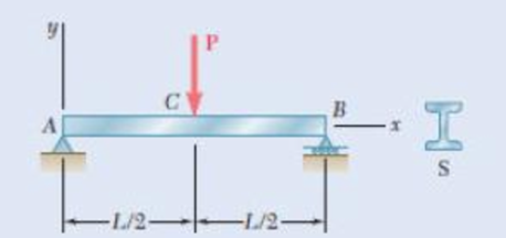
Fig. P9.10
Expert Solution & Answer
Want to see the full answer?
Check out a sample textbook solution
Students have asked these similar questions
CE-112 please solve this problem step by step and give me the correct answer
CE-112 please solve this problem step by step and give me the correct answer
CE-112 solve this problem step by step and give me the correct answer please
Chapter 9 Solutions
Mechanics of Materials, 7th Edition
Ch. 9.2 - In the following problems assume that the flexural...Ch. 9.2 - In the following problems assume that the flexural...Ch. 9.2 - In the following problems assume that the flexural...Ch. 9.2 - 9.1 through 9.4 For the loading shown, determine...Ch. 9.2 - 9.5 and 9.6 For the cantilever beam and loading...Ch. 9.2 - 9.5 and 9.6 For the cantilever beam and loading...Ch. 9.2 - For the beam and loading shown, determine (a) the...Ch. 9.2 - For the beam and loading shown, determine (a) the...Ch. 9.2 - Knowing that beam .AB is a W10 33 rolled shape...Ch. 9.2 - Knowing that beam AB is an S200 34 roiled shape...
Ch. 9.2 - For the beam and loading shown, (a) express the...Ch. 9.2 - (a) Determine the location and magnitude of the...Ch. 9.2 - For the beam and loading shown, determine the...Ch. 9.2 - Knowing that beam AE is a W360 101 rolled shape...Ch. 9.2 - For the beam and loading shown, knowing that a = 2...Ch. 9.2 - Knowing that beam AE is an S200 27.4 rolled shape...Ch. 9.2 - For the beam and loading shown, determine (a) the...Ch. 9.2 - For the beam and loading shown, determine (a) the...Ch. 9.2 - 9.19 through 9.22 For the beam and loading shown,...Ch. 9.2 - 9.19 through 9.22 For the beam and loading shown,...Ch. 9.2 - 9.19 through 9.22 For the beam and loading shown,...Ch. 9.2 - 9.19 through 9.22 For the beam and loading shown,...Ch. 9.2 - For the beam shown, determine the reaction at the...Ch. 9.2 - For the beam shown, determine the reaction at the...Ch. 9.2 - 9.25 through 9.28 Determine the reaction at the...Ch. 9.2 - 9.25 through 9.28 Determine the reaction at the...Ch. 9.2 - Prob. 27PCh. 9.2 - 9.25 through 9.28 Determine the reaction at the...Ch. 9.2 - 9.29 and 9.30 Determine the reaction at the roller...Ch. 9.2 - 9.29 and 9.30 Determine the reaction at the roller...Ch. 9.2 - 9.37 and 9.32 Determine the reaction at the roller...Ch. 9.2 - 9.31 and 9.32 Determine the reaction at the roller...Ch. 9.2 - Prob. 33PCh. 9.2 - 9.33 and 9.34 determine the reaction at A and draw...Ch. 9.3 - 9.35 and 9.36 For the beam and loading shown,...Ch. 9.3 - 9.35 and 9.36 For the beam and loading shown,...Ch. 9.3 - 9.37 and 9.38 For the beam and loading shown,...Ch. 9.3 - 9.37 and 9.38 For the beam and loading shown,...Ch. 9.3 - 9.39 and 9.40 For the beam and loading shown,...Ch. 9.3 - 9.39 and 9.40 For the beam and loading shown,...Ch. 9.3 - 9.41 and 9.42 For the beam and loading shown,...Ch. 9.3 - 9.41 and 9.42 For the beam and loading shown (a)...Ch. 9.3 - For the beam and loading shown, determine (a) the...Ch. 9.3 - For the beam and loading shown, determine (a) the...Ch. 9.3 - For the timber beam and loading shown, determine...Ch. 9.3 - For the beam and loading shown, determine (a) the...Ch. 9.3 - For the beam and loading shown, determine (a) the...Ch. 9.3 - For the beam and loading shown, determine (a) the...Ch. 9.3 - 9.49 and 9.50 For the beam and loading shown,...Ch. 9.3 - 9.49 and 9.50 For the beam and loading shown,...Ch. 9.3 - 9.51 and 9.52 For the beam and loading shown,...Ch. 9.3 - 9.49 and 9.50 For the beam and loading shown,...Ch. 9.3 - For the beam and loading shown, determine (a) the...Ch. 9.3 - For the beam shown, and knowing that P = 40 kN,...Ch. 9.3 - 9.55 and 9.56 For the beam and loading shown, (a)...Ch. 9.3 - 9.55 and 9.56 For the beam and loading shown, (a)...Ch. 9.3 - For the beam and loading shown, determine (a) the...Ch. 9.3 - For the beam and loading shown, determine (a) the...Ch. 9.3 - Prob. 59PCh. 9.3 - 9.59 through 9.62 For the beam and loading...Ch. 9.3 - Prob. 61PCh. 9.3 - 9.59 through 9.62 For the beam and loading...Ch. 9.3 - The rigid bars BF and DH are welded to the...Ch. 9.3 - The rigid bar DEF is welded at point D to the...Ch. 9.4 - Use the method of superposition to solve the...Ch. 9.4 - Use the method of superposition to solve the...Ch. 9.4 - Use the method of superposition to solve the...Ch. 9.4 - Use the method of superposition to solve the...Ch. 9.4 - Use the method of superposition to solve the...Ch. 9.4 - Use the method of superposition to solve the...Ch. 9.4 - Use the method of superposition to solve the...Ch. 9.4 - Use the method of superposition to solve the...Ch. 9.4 - Use the method of superposition to solve the...Ch. 9.4 - Use the method of superposition to solve the...Ch. 9.4 - Use the method of superposition to solve the...Ch. 9.4 - Use the method of superposition to solve the...Ch. 9.4 - Use the method of superposition to solve the...Ch. 9.4 - Use the method of superposition to solve the...Ch. 9.4 - Use the method of superposition to solve the...Ch. 9.4 - Use the method of superposition to solve the...Ch. 9.4 - Use the method of superposition to solve the...Ch. 9.4 - Use the method of superposition to solve the...Ch. 9.4 - Use the method of superposition to solve the...Ch. 9.4 - Prob. 84PCh. 9.4 - Use the method of superposition to solve the...Ch. 9.4 - Use the method of superposition to solve the...Ch. 9.4 - Use the method of superposition to solve the...Ch. 9.4 - Use the method of superposition to solve the...Ch. 9.4 - Use the method of superposition to solve the...Ch. 9.4 - Use the method of superposition to solve the...Ch. 9.4 - Use the method of superposition to solve the...Ch. 9.4 - Use the method of superposition to solve the...Ch. 9.4 - Use the method of superposition to solve the...Ch. 9.4 - Use the method of superposition to solve the...Ch. 9.5 - 9.95 through 9.98 For the uniform cantilever beam...Ch. 9.5 - Prob. 96PCh. 9.5 - 9.95 through 9.98 For the uniform cantilever beam...Ch. 9.5 - 9.95 through 9.98 For the uniform cantilever beam...Ch. 9.5 - 9.99 and 9.100 For the uniform cantilever beam and...Ch. 9.5 - 9.99 and 9.100 For the uniform cantilever beam and...Ch. 9.5 - For the cantilever beam and loading shown,...Ch. 9.5 - Prob. 102PCh. 9.5 - Prob. 103PCh. 9.5 - Prob. 104PCh. 9.5 - Prob. 105PCh. 9.5 - For the cantilever beam and loading shown,...Ch. 9.5 - Two cover plates are welded to the rolled-steel...Ch. 9.5 - Two cover plates are welded to the rolled-steel...Ch. 9.5 - 9.109 through 9.114 For the prismatic beam and...Ch. 9.5 - Prob. 110PCh. 9.5 - Prob. 111PCh. 9.5 - Prob. 112PCh. 9.5 - Prob. 113PCh. 9.5 - Prob. 114PCh. 9.5 - Prob. 115PCh. 9.5 - 9.115 and 9.116 For the beam and loading shown,...Ch. 9.5 - Prob. 117PCh. 9.5 - 9.118 and 9.119 For the beam and loading shown,...Ch. 9.5 - Prob. 119PCh. 9.5 - Prob. 120PCh. 9.5 - Prob. 121PCh. 9.5 - Prob. 122PCh. 9.5 - Prob. 123PCh. 9.5 - Prob. 124PCh. 9.6 - 9.125 through 9.128 For the prismatic beam and...Ch. 9.6 - Prob. 126PCh. 9.6 - Prob. 127PCh. 9.6 - Prob. 128PCh. 9.6 - 9.129 and 9.130 For the beam and loading shown,...Ch. 9.6 - Prob. 130PCh. 9.6 - For the timber beam and loading shown, determine...Ch. 9.6 - Prob. 132PCh. 9.6 - For the beam and loading shown, determine (a) the...Ch. 9.6 - Prob. 134PCh. 9.6 - Prob. 135PCh. 9.6 - Knowing that the beam AD is made of a solid steel...Ch. 9.6 - Prob. 137PCh. 9.6 - For the beam and loading shown, determine (a) the...Ch. 9.6 - Prob. 139PCh. 9.6 - For the beam and loading shown, determine the...Ch. 9.6 - Prob. 141PCh. 9.6 - Prob. 142PCh. 9.6 - Prob. 143PCh. 9.6 - Prob. 144PCh. 9.6 - Prob. 145PCh. 9.6 - For the beam and loading shown, determine (a) the...Ch. 9.6 - Prob. 147PCh. 9.6 - Prob. 148PCh. 9.6 - Prob. 149PCh. 9.6 - Prob. 150PCh. 9.6 - 9.151 and 9.152 For the beam and loading shown,...Ch. 9.6 - Prob. 152PCh. 9.6 - Prob. 153PCh. 9.6 - Prob. 154PCh. 9.6 - Prob. 155PCh. 9.6 - Fig. P9.155 and P9.156 9.156 For the beam and...Ch. 9 - For the loading shown, determine (a) the equation...Ch. 9 - Prob. 158RPCh. 9 - For the beam and loading shown, determine (a) the...Ch. 9 - Determine the reaction at A and draw the bending...Ch. 9 - For the beam and loading shown, determine (a) the...Ch. 9 - For the beam and loading shown, determine (a) the...Ch. 9 - Beam CE rests on beam AB as shown. Knowing that a...Ch. 9 - The cantilever beam BC is attached to the steel...Ch. 9 - For the cantilever beam and loading shown,...Ch. 9 - Knowing that P = 4 kips, determine (a) the slope...Ch. 9 - For the beam and loading shown, determine (a) the...Ch. 9 - Determine the reaction at the roller support and...
Knowledge Booster


Learn more about
Need a deep-dive on the concept behind this application? Look no further. Learn more about this topic, mechanical-engineering and related others by exploring similar questions and additional content below.Similar questions
- Please do not use any AI tools to solve this question. I need a fully manual, step-by-step solution with clear explanations, as if it were done by a human tutor. No AI-generated responses, please.arrow_forwardPlease do not use any AI tools to solve this question. I need a fully manual, step-by-step solution with clear explanations, as if it were done by a human tutor. No AI-generated responses, please.arrow_forwardCE-112 please solve this problem step by step and give me the correct answerarrow_forward
- CE-112 please solve this problem step by step and give me the correct asnwerarrow_forwardthis is an old practice exam, the answer is Ax = -4, Ay = -12,Az = 32.5, Bx= 34, Bz = 5, By = 0 but how?arrow_forwardThis is an old practice exam, the answer is Ax = Az = 0, Ay = 2000, TDE = 4750, Cx = 2000, Cy = 2000, Cz = -800 but how?arrow_forward
- this is an old practice exam, the answer is Fmin = 290.5lb but howarrow_forwardThis is an exam review question. The answer is Pmin = 622.9 lb but whyarrow_forwardPlease do not use any AI tools to solve this question. I need a fully manual, step-by-step solution with clear explanations, as if it were done by a human tutor. No AI-generated responses, please.arrow_forward
- Please do not use any AI tools to solve this question. I need a fully manual, step-by-step solution with clear explanations, as if it were done by a human tutor. No AI-generated responses, please.arrow_forwardPlease do not use any AI tools to solve this question. I need a fully manual, step-by-step solution with clear explanations, as if it were done by a human tutor. No AI-generated responses, please.arrow_forwardThis is an old practice exam. Fce = 110lb and FBCD = 62 lb but whyarrow_forward
arrow_back_ios
SEE MORE QUESTIONS
arrow_forward_ios
Recommended textbooks for you
 International Edition---engineering Mechanics: St...Mechanical EngineeringISBN:9781305501607Author:Andrew Pytel And Jaan KiusalaasPublisher:CENGAGE L
 Mechanics of Materials (MindTap Course List)Mechanical EngineeringISBN:9781337093347Author:Barry J. Goodno, James M. GerePublisher:Cengage Learning
 Principles of Heat Transfer (Activate Learning wi...Mechanical EngineeringISBN:9781305387102Author:Kreith, Frank; Manglik, Raj M.Publisher:Cengage Learning
International Edition---engineering Mechanics: St...
Mechanical Engineering
ISBN:9781305501607
Author:Andrew Pytel And Jaan Kiusalaas
Publisher:CENGAGE L
Mechanics of Materials (MindTap Course List)
Mechanical Engineering
ISBN:9781337093347
Author:Barry J. Goodno, James M. Gere
Publisher:Cengage Learning
Principles of Heat Transfer (Activate Learning wi...
Mechanical Engineering
ISBN:9781305387102
Author:Kreith, Frank; Manglik, Raj M.
Publisher:Cengage Learning
Solids: Lesson 53 - Slope and Deflection of Beams Intro; Author: Jeff Hanson;https://www.youtube.com/watch?v=I7lTq68JRmY;License: Standard YouTube License, CC-BY