
Loose Leaf for Engineering Circuit Analysis Format: Loose-leaf
9th Edition
ISBN: 9781259989452
Author: Hayt
Publisher: Mcgraw Hill Publishers
expand_more
expand_more
format_list_bulleted
Concept explainers
Videos
Textbook Question
Chapter 9.2, Problem 2P
After being open for a long time, the switch in Fig. 9.6 closes at t = 0. Find (a) iL(0−); (b) vC(0−); (c) iR(0+); (d) iC(0+); (e) vC(0.2).
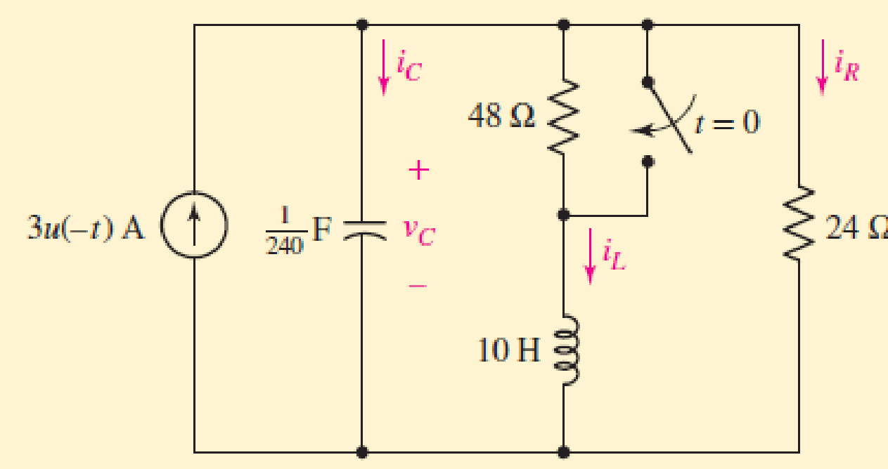
FIGURES 9.6
Expert Solution & Answer
Want to see the full answer?
Check out a sample textbook solution
Students have asked these similar questions
4v+9v+8v=-3v+6v',-5v,
where vi and vo are the input and output voltage, respectively.
I decided to focus on the magnitude where I do the normalization on low and high pass and have the bandpass as dB(dB(decibel), with frequency cutoff, I manage to get accurate but have trouble controlling the frequency cutoff accurately and the bandbass isn't working properly. As such I need help.My Code:
% Define frequency range for the plot
f = logspace(1, 5, 500); % Frequency range from 10 Hz to 100 kHz
w = 2 * pi * f; % Angular frequency
% Parameters for the filters
R = 1e3; % Resistance in ohms (1 kΩ)
C = 1e-6; % Capacitance in farads (1 μF)
L = 10e-3; % Inductance in henries (10 mH)
% Transfer functions
H_low = 1 ./ (1 + 1i * w * R * C); % Low-pass filter
H_high = (1i * w * R * C) ./ (1 + 1i * w * R * C); % High-pass filter
H_band = (1i * w * R * C) ./ (1 + 1i * w * L / R + 1i * w * R * C); % Band-pass filter
% Cutoff frequency for RC filters (Low-pass and High-pass)
f_cutoff_RC = 1 / (2 * pi * R * C);
% Band-pass filter cutoff frequencies
f_lower_cutoff = 1 / (2 * pi *…
Please do NOT answer if you are going to use AI. Please give a proper solution.
Chapter 9 Solutions
Loose Leaf for Engineering Circuit Analysis Format: Loose-leaf
Ch. 9.1 - A parallel RLC circuit contains a 100 2 resistor...Ch. 9.2 - After being open for a long time, the switch in...Ch. 9.2 - Prob. 3PCh. 9.2 - Prob. 4PCh. 9.3 - (a) Choose R1 in the circuit of Fig. 9.14 so that...Ch. 9.4 - Prob. 6PCh. 9.5 - Prob. 7PCh. 9.5 - Prob. 8PCh. 9.6 - Let is = 10u(t) 20u(t) A in Fig. 9.31. Find (a)...Ch. 9.6 - Let vs = 10 + 20u(t) V in the circuit of Fig....
Ch. 9.7 - Alter the capacitor value and voltage source in...Ch. 9 - For a certain source-free parallel RLC circuit, R...Ch. 9 - Element values of 10 mF and 2 nH are employed in...Ch. 9 - If a parallel RLC circuit is constructed from...Ch. 9 - Prob. 4ECh. 9 - You go to construct the circuit in Exercise 1,...Ch. 9 - A parallel RLC circuit has inductance 2 mH and...Ch. 9 - Prob. 7ECh. 9 - A parallel RLC circuit has R = 1 k, L = 50 mH. and...Ch. 9 - Prob. 9ECh. 9 - Prob. 10ECh. 9 - The current flowing through a 5 resistor in a...Ch. 9 - For the circuit of Fig.9.40, obtain an expression...Ch. 9 - Consider the circuit depicted in Fig. 9.40. (a)...Ch. 9 - With regard to the circuit represented in Fig....Ch. 9 - (a) Assuming the passive sign convention, obtain...Ch. 9 - With regard to the circuit presented in Fig. 9.42,...Ch. 9 - Obtain expressions for the current i(t) and...Ch. 9 - FIGURE 9.43 Replace the 14 resistor in the...Ch. 9 - Design a complete source-free parallel RLC circuit...Ch. 9 - For the circuit represented by Fig. 9.44, the two...Ch. 9 - Prob. 21ECh. 9 - Prob. 22ECh. 9 - A critically damped parallel RLC circuit is...Ch. 9 - A source-free parallel RLC circuit has an initial...Ch. 9 - A critically damped parallel RLC circuit is...Ch. 9 - For the circuit of Fig. 9.45, is(t) = 30u(t) mA....Ch. 9 - Prob. 27ECh. 9 - The circuit of Fig. 9.44 is rebuilt such that the...Ch. 9 - Prob. 29ECh. 9 - Prob. 30ECh. 9 - The source-free circuit depicted in Fig. 9.1 is...Ch. 9 - (a) Graph the current i for the circuit described...Ch. 9 - Analyze the circuit described in Exercise 31 to...Ch. 9 - A source-free parallel RLC circuit has capacitance...Ch. 9 - Prob. 35ECh. 9 - Obtain an expression for vL(t), t 0, for the...Ch. 9 - For the circuit of Fig. 9.47, determine (a) the...Ch. 9 - (a) Design a parallel RLC circuit that provides a...Ch. 9 - The circuit depicted in Fig. 9.48 is just barely...Ch. 9 - When constructing the circuit of Fig. 9.48, you...Ch. 9 - The circuit of Fig. 9.22a is constructed with a...Ch. 9 - Prob. 42ECh. 9 - Prob. 43ECh. 9 - The simple three-element series RLC circuit of...Ch. 9 - Prob. 45ECh. 9 - Prob. 46ECh. 9 - Prob. 47ECh. 9 - With reference to the series RLC circuit of Fig....Ch. 9 - Obtain an expression for i1 as labeled in Fig....Ch. 9 - The circuit in Fig. 9.52 has the switch in...Ch. 9 - For the circuit in Fig. 9.52, determine the value...Ch. 9 - In the series circuit of Fig. 9.53, set R = 1 ....Ch. 9 - Evaluate the derivative of each current and...Ch. 9 - Consider the circuit depicted in Fig. 9.55. If...Ch. 9 - Prob. 55ECh. 9 - In the circuit shown in Fig. 9.56, (a) obtain an...Ch. 9 - Prob. 57ECh. 9 - For the circuit represented in Fig. 9.57, (a)...Ch. 9 - FIGURE 9.57 Replace the 1 resistor in Fig. 9.57...Ch. 9 - A circuit has an inductive load of 2 H, a...Ch. 9 - (a) Adjust the value of the 3 resistor in the...Ch. 9 - Determine expressions for vC(t) and iL(t) in Fig....Ch. 9 - The capacitor in the LC circuit in Fig. 9.60 has...Ch. 9 - Suppose that the switch in the circuit in Fig....Ch. 9 - The capacitor in the circuit of Fig. 9.63 is set...Ch. 9 - The physical behavior of automotive suspension...Ch. 9 - A lossless LC circuit can be used to provide...
Knowledge Booster


Learn more about
Need a deep-dive on the concept behind this application? Look no further. Learn more about this topic, electrical-engineering and related others by exploring similar questions and additional content below.Similar questions
- P7.2 The capacitors in the circuit shown below have no energy stored in them and then switch "A" closes at time t=0. Switch "B" closes 2.5 milliseconds later. Find v(t) across the 6 μF capacitor for t≥ 0. 500 Ω B 4 µF 20 V 6 µF 7 Σ2 ΚΩ 25 mA + · μεarrow_forwardQ1: If x[n] is a discrete signal and represented by the following equation, what is the value of x[0] and X[-2] Q2: {x[n]}={-0.2,2.2,1.1,0.2,-3.7,2.9,...} a- Assuming that a 5-bit ADC channel accepts analog input ranging from 0 to 4 volts, determine the following: 1- number of quantization levels; 2-step size of the quantizer or resolution; 3- quantization level when the analog voltage is 1.28 volts. 4- binary code produced by the ADC. 5- quantization error. b- Determine whether the linear system is time invariant or not? 1 1 y(n) = x(n) Q3: Evaluate the digital convolution of the following signals using Graphical method. Find: y(0) to y(3) Q4: 2, k = 0,1,2 2, k = 0 h(k) 0 1, k = 3,4 and x(k) elsewhere = 1, k = 1,2 0 elsewhere The temperature (in Kelvin) of an electronic component can be modelled using the following approximation: T(t) [293+15e-Ju(t) A digital thermometer is used to periodically record the component's temperature, taking a sample every 5 seconds. 1- Represent the…arrow_forwardI need solution by hand clearlyarrow_forward
- fin D Q Point 7.57 in Matlab Aarrow_forwardFor the following graphical figure, write the function x(n) and h(n) in: 1. sequential vector 2. functional representation 3. Tabular 2 h0) 32 If signal x(n)-(32130 104032)], describe this signal using: 1. Graphical representation 2. Tabular representation 3. Write its expression 4. Write it as equation 5. Draw it as y(n) - x(n) u(n-3) 6. Sketch it if it is bounded at -2arrow_forwardFor the following Split-phase Manchester waveform, extract the original binary data. Then draw the AMI code for that data. 0arrow_forward1 ΚΩ N₁ m ZL (10+j4) ks2 178/0° V N2 -202 Ω Figure P11.31 Circuit for Problem 11.31.arrow_forwardCari induktasi saluran transmisi terhadapku GMDarrow_forwardA wattmeter is connected with the positive lead on phase “a” of a three-phase system. The negative lead is connected to phase “b”. A separate wattmeter has the positive lead connected to phase “c”. The negative lead of this wattmeter is connected also to phase “b”. If the input voltage is 208 volts line-to-line, the phase sequence is “abc” and the load is 1200 ohm resistors connected in “Y”, what is the expected reading of each of the wattmeters? (Hint: draw a phasor diagram)arrow_forwardarrow_back_iosSEE MORE QUESTIONSarrow_forward_ios
Recommended textbooks for you
 Introductory Circuit Analysis (13th Edition)Electrical EngineeringISBN:9780133923605Author:Robert L. BoylestadPublisher:PEARSON
 Delmar's Standard Textbook Of ElectricityElectrical EngineeringISBN:9781337900348Author:Stephen L. HermanPublisher:Cengage Learning
 Programmable Logic ControllersElectrical EngineeringISBN:9780073373843Author:Frank D. PetruzellaPublisher:McGraw-Hill Education
 Fundamentals of Electric CircuitsElectrical EngineeringISBN:9780078028229Author:Charles K Alexander, Matthew SadikuPublisher:McGraw-Hill Education
 Electric Circuits. (11th Edition)Electrical EngineeringISBN:9780134746968Author:James W. Nilsson, Susan RiedelPublisher:PEARSON
 Engineering ElectromagneticsElectrical EngineeringISBN:9780078028151Author:Hayt, William H. (william Hart), Jr, BUCK, John A.Publisher:Mcgraw-hill Education,
Introductory Circuit Analysis (13th Edition)
Electrical Engineering
ISBN:9780133923605
Author:Robert L. Boylestad
Publisher:PEARSON
Delmar's Standard Textbook Of Electricity
Electrical Engineering
ISBN:9781337900348
Author:Stephen L. Herman
Publisher:Cengage Learning
Programmable Logic Controllers
Electrical Engineering
ISBN:9780073373843
Author:Frank D. Petruzella
Publisher:McGraw-Hill Education
Fundamentals of Electric Circuits
Electrical Engineering
ISBN:9780078028229
Author:Charles K Alexander, Matthew Sadiku
Publisher:McGraw-Hill Education
Electric Circuits. (11th Edition)
Electrical Engineering
ISBN:9780134746968
Author:James W. Nilsson, Susan Riedel
Publisher:PEARSON
Engineering Electromagnetics
Electrical Engineering
ISBN:9780078028151
Author:Hayt, William H. (william Hart), Jr, BUCK, John A.
Publisher:Mcgraw-hill Education,
ENA 9.2(1)(En)(Alex) Sinusoids & Phasors - Explanation with Example 9.1 ,9.2 & PP 9.2; Author: Electrical Engineering Academy;https://www.youtube.com/watch?v=vX_LLNl-ZpU;License: Standard YouTube License, CC-BY
Electrical Engineering: Ch 10 Alternating Voltages & Phasors (8 of 82) What is a Phasor?; Author: Michel van Biezen;https://www.youtube.com/watch?v=2I1tF3ixNg0;License: Standard Youtube License