Videos
a)
The pressure at the turbine exit.
a)
Answer to Problem 133P
The pressure at the turbine exit is
Explanation of Solution
Draw the
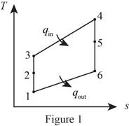
Consider that the aircraft is stationary, and the velocity of air moving towards the aircraft is
Diffuser (For process 1-2):
Write the expression for the energy balance equation for the diffuser.
Here, the rate of energy entering the system is
Write the temperature and pressure relation for the process 1-2.
Here, the specific heat ratio of air is k, pressure at state 1 is
Compressor (For process 2-3)
Write the pressure relation using the pressure ratio for the process 2-3.
Here, the pressure ratio is
Write the temperature and pressure relation for the process 2-3.
Here, temperate at state 3 is
Turbine (For process 4-5)
Write the temperature relation for the compressor and turbine.
Here, the specific heat at constant pressure is
Write the temperature and pressure relation for the process 4-5.
Conclusion:
From Table A-2E, “Ideal-gas specific heats of various common gases”, obtain the following values for air at room temperature.
The rate of change in the energy of the system
Substitute
Here, inlet velocity is
Substitute 0 for
Substitute
Substitute 13 for
Substitute 537.4 R for
Substitute
Substitute
Thus, the pressure at the turbine exit is
b)
The exit velocity of the exhaust gases.
b)
Answer to Problem 133P
The exit velocity of the exhaust gases is
Explanation of Solution
Nozzle (For process 5-6)
Write the temperature and pressure relation for the isentropic process 4-6.
Here, pressure at state 6 is
Write the energy balance equation for the nozzle.
Conclusion:
Substitute
The rate of change in the energy of the system
Substitute
Here, velocity at stat 5 is
Since,
Substitute
Thus, the exit velocity of the exhaust gases is
c)
The propulsive efficiency of the turbojet engine.
c)
Answer to Problem 133P
The propulsive efficiency of the turbojet engine is
Explanation of Solution
Write the expression to calculate the propulsive work done per unit mass by the turbojet engine
Here, the velocity of the aircraft is
Write the expression to calculate the heating value of the fuel per unit mass for the turbojet engine
Here, temperature at state 4 is
Write the expression to calculate the propulsive efficiency of the turbojet engine
Conclusion.
Substitute
Substitute
Substitute
Thus, the propulsive efficiency of the turbojet engine is
Want to see more full solutions like this?
Chapter 9 Solutions
Thermodynamics: An Engineering Approach


- Part A: Suppose you wanted to drill a 1.5 in diameter hole through a piece of 1020 cold-rolled steel that is 2 in thick, using an HSS twist drill. What values if feed and cutting speed will you specify, along with an appropriate allowance? Part B: How much time will be required to drill the hole in the previous problem using the HSS drill?arrow_forward1.1 m 1.3 m B 60-mm diameter Brass 40-mm diameter Aluminum PROBLEM 2.52 - A rod consisting of two cylindrical portions AB and BC is restrained at both ends. Portion AB is made of brass (E₁ = 105 GPa, α = 20.9×10°/°C) and portion BC is made of aluminum (Ę₁ =72 GPa, α = 23.9×10/°C). Knowing that the rod is initially unstressed, determine (a) the normal stresses induced in portions AB and BC by a temperature rise of 42°C, (b) the corresponding deflection of point B.arrow_forward30 mm D = 40 MPa -30 mm B C 80 MPa PROBLEM 2.69 A 30-mm square was scribed on the side of a large steel pressure vessel. After pressurization, the biaxial stress condition at the square is as shown. For E = 200 GPa and v=0.30, determine the change in length of (a) side AB, (b) side BC, (c) diagnonal AC.arrow_forward
- Please solve in detail this problem thank youarrow_forward0,5 mm 450 mm 350 mm Bronze A = 1500 mm² E = 105 GPa प 21.6 × 10-PC Aluminum A = 1800 mm² £ = 73 GPa = a 23.2 × 10-PC PROBLEM 2.58 Knowing that a 0.5-mm gap exists when the temperature is 24°C, determine (a) the temperature at which the normal stress in the aluminum bar will be equal to -75 MPa, (b) the corresponding exact length of the aluminum bar.arrow_forward0.5 mm 450 mm -350 mm Bronze Aluminum A 1500 mm² A 1800 mm² E 105 GPa E 73 GPa K = 21.6 X 10 G < = 23.2 × 10-G PROBLEM 2.59 Determine (a) the compressive force in the bars shown after a temperature rise of 82°C, (b) the corresponding change in length of the bronze bar.arrow_forward
- The truss shown below sits on a roller at A and a pin at E. Determine the magnitudes of the forces in truss members GH, GB, BC and GC. State whether they are in tension or compression or are zero force members.arrow_forwardA weight (W) hangs from a pulley at B that is part of a support frame. Calculate the maximum possible mass of the weight if the maximum permissible moment reaction at the fixed support is 100 Nm. Note that a frictionless pin in a slot is located at C.arrow_forwardIt is the middle of a winter snowstorm. Sally and Jin take shelter under an overhang. The loading of the snow on top of the overhang is shown in the figure below. The overhang is attached to the wall at points A and B with pin supports. Another pin is at C. Determine the reactions of the pin supports at A and B. Express them in Cartesian vector form.arrow_forward
- Recall that the CWH equation involves two important assumptions. Let us investigate how these assumptions affect the accuracy of state trajectories under the control inputs optimized in (a) and (b). (c.1): Discuss the assumptions about the chief and deputy orbits that are necessary for deriving CWH.arrow_forwardPROBLEM 2.50 1.8 m The concrete post (E-25 GPa and a = 9.9 x 10°/°C) is reinforced with six steel bars, each of 22-mm diameter (E, = 200 GPa and a, = 11.7 x 10°/°C). Determine the normal stresses induced in the steel and in the concrete by a temperature rise of 35°C. 6c " 0.391 MPa 240 mm 240 mm 6₁ = -9.47 MPaarrow_forwardFor some viscoelastic polymers that are subjected to stress relaxation tests, the stress decays with time according to a(t) = a(0) exp(-4) (15.10) where σ(t) and o(0) represent the time-dependent and initial (i.e., time = 0) stresses, respectively, and t and T denote elapsed time and the relaxation time, respectively; T is a time-independent constant characteristic of the material. A specimen of a viscoelastic polymer whose stress relaxation obeys Equation 15.10 was suddenly pulled in tension to a measured strain of 0.5; the stress necessary to maintain this constant strain was measured as a function of time. Determine E (10) for this material if the initial stress level was 3.5 MPa (500 psi), which dropped to 0.5 MPa (70 psi) after 30 s.arrow_forward
 Elements Of ElectromagneticsMechanical EngineeringISBN:9780190698614Author:Sadiku, Matthew N. O.Publisher:Oxford University Press
 Mechanics of Materials (10th Edition)Mechanical EngineeringISBN:9780134319650Author:Russell C. HibbelerPublisher:PEARSON
 Thermodynamics: An Engineering ApproachMechanical EngineeringISBN:9781259822674Author:Yunus A. Cengel Dr., Michael A. BolesPublisher:McGraw-Hill Education
 Control Systems EngineeringMechanical EngineeringISBN:9781118170519Author:Norman S. NisePublisher:WILEY
 Mechanics of Materials (MindTap Course List)Mechanical EngineeringISBN:9781337093347Author:Barry J. Goodno, James M. GerePublisher:Cengage Learning
 Engineering Mechanics: StaticsMechanical EngineeringISBN:9781118807330Author:James L. Meriam, L. G. Kraige, J. N. BoltonPublisher:WILEY