
Vector Mechanics for Engineers: Statics
12th Edition
ISBN: 9781259977268
Author: Ferdinand P. Beer, E. Russell Johnston Jr., David Mazurek
Publisher: McGraw-Hill Education
expand_more
expand_more
format_list_bulleted
Videos
Textbook Question
Chapter 9.1, Problem 9.1P
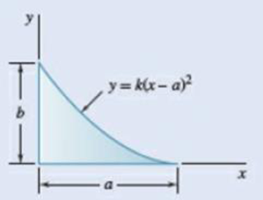
9.1 through 9.4 Determine by direct integration the moment of inertia of the shaded area with respect to y axis.
Expert Solution & Answer
Want to see the full answer?
Check out a sample textbook solution
Students have asked these similar questions
In (Figure 1), take m₁ = 4 kg and mB = 4.6 kg.
Determine the z component of the angular momentum Ho of particle A about point O.
Determine the z component of the angular momentum Ho of particle B about point O. Suppose that
5 m
8 m/s
4 m
1.5 m
4 m
B
MB
1 m
2 m
5
30°
6 m/s
MA
The two disks A and B have a mass of 4 kg and 6 kg,
respectively. They collide with the initial velocities shown. The
coefficient of restitution is e = 0.75. Suppose that
(VA)1 = 6 m/s, (VB)₁ = 7 m/s. (Figure 1)
Determine the magnitude of the velocity of A just after impact.
Determine the angle between the x axis and the velocity of A just after impact, measured clockwise from the negative x axis.
Determine the magnitude of the velocity of B just after impact.
Determine the angle between the x axis and the velocity of B just after impact, measured clockwise from the positive x axis.
(VB)1
B
(VA)1
60°
Line of impact
A hot plane surface is maintained at 100°C, and it is exposed to air at 25°C.The combined heat transfer coefficient between the surface and the air is 25W/m²·K. (same as above). In this task, you are asked to design fins to cool asurface by attaching 3 cm-long, 0.25 cm-diameter aluminum pin fins (thermalconductivity, k = 237 W/m·K) with a center-to-center distance of 0.6 cm. (Tip:do not correct the length). Determine the rate of heat transfer from thefinned structure to the air for a 1 m x 1 m section of the plate.
Chapter 9 Solutions
Vector Mechanics for Engineers: Statics
Ch. 9.1 - 9.1 through 9.4 Determine by direct integration...Ch. 9.1 - 9.1 through 9.4 Determine by direct integration...Ch. 9.1 - 9.1 through 9.4 Determine by direct integration...Ch. 9.1 - 9.1 through 9.4 Determine by direct integration...Ch. 9.1 - 9.5 through 9.8 Determine by direct integration...Ch. 9.1 - 9.5 through 9.8 Determine by direct integration...Ch. 9.1 - 9.5 through 9.8 Determine by direct integration...Ch. 9.1 - 9.5 through 9.8 Determine by direct integration...Ch. 9.1 - 9.9 through 9.11 Determine by direct integration...Ch. 9.1 - 9.9 through 9.11 Determine by direct integration...
Ch. 9.1 - 9.9 through 9.11 Determine by direct integration...Ch. 9.1 - 9.12 through 9.14 Determine by direct integration...Ch. 9.1 - Prob. 9.13PCh. 9.1 - 9.12 through 9.14 Determine by direct integration...Ch. 9.1 - 9.15 and 9.16 Determine the moment of inertia and...Ch. 9.1 - Prob. 9.16PCh. 9.1 - 9.17 and 9.18 Determine the moment of inertia and...Ch. 9.1 - Prob. 9.18PCh. 9.1 - Determine the moment of inertia and the radius of...Ch. 9.1 - Prob. 9.20PCh. 9.1 - Prob. 9.21PCh. 9.1 - Determine the polar moment of inertia and the...Ch. 9.1 - 9.23 and 9.24 Determine the polar moment of...Ch. 9.1 - 9.23 and 9.24 Determine the polar moment of...Ch. 9.1 - (a) Determine by direct integration the polar...Ch. 9.1 - (a) Show that the polar radius of gyration kQ of...Ch. 9.1 - Determine the polar moment of inertia and the...Ch. 9.1 - Determine the polar moment of inertia and the...Ch. 9.1 - Using the polar moment of inertia of the isosceles...Ch. 9.1 - Prove that the centroidal polar moment of inertia...Ch. 9.2 - 9.31 and 9.32 Determine the moment of inertia and...Ch. 9.2 - 9.31 and 9.32 Determine the moment of inertia and...Ch. 9.2 - 9.33 and 9.34 Determine the moment of inertia and...Ch. 9.2 - 9.33 and 9.34 Determine the moment of inertia and...Ch. 9.2 - Prob. 9.35PCh. 9.2 - Determine the moments of inertia of the shaded...Ch. 9.2 - Prob. 9.37PCh. 9.2 - Fig. P9.37 and P9.38 9.38 Knowing that the shaded...Ch. 9.2 - Prob. 9.39PCh. 9.2 - Fig. P9.39 and P9.40 9.40 The polar moments of...Ch. 9.2 - Prob. 9.41PCh. 9.2 - 9.41 through 9.44 Determine the moments of inertia...Ch. 9.2 - 9.41 through 9.44 Determine the moments of inertia...Ch. 9.2 - 9.41 through 9.44 Determine the moments of inertia...Ch. 9.2 - 9.45 and 9.46 Determine the polar moment of...Ch. 9.2 - 9.45 and 9.46 Determine the polar moment of...Ch. 9.2 - Prob. 9.47PCh. 9.2 - Prob. 9.48PCh. 9.2 - Prob. 9.49PCh. 9.2 - Prob. 9.50PCh. 9.2 - Four L3 3 14 - in. angles are welded to a rolled...Ch. 9.2 - Two 20-mm steel plates are welded to a rolled S...Ch. 9.2 - A channel and a plate are welded together as shown...Ch. 9.2 - The strength of the rolled W section shown is...Ch. 9.2 - Two L76 76 6.4-mm angles are welded to a C250 ...Ch. 9.2 - Two steel plates are welded to a rolled W section...Ch. 9.2 - 9.57 and 9.58 The panel shown forms the end of a...Ch. 9.2 - 9.57 and 9.58 The panel shown forms the end of a...Ch. 9.2 - 9.59 and 9.60 The panel shown forms the end of a...Ch. 9.2 - 9.59 and 9.60 The panel shown forms the end of a...Ch. 9.2 - A vertical trapezoidal gate that is used as an...Ch. 9.2 - The cover for a 0.5-m-diameter access hole in a...Ch. 9.2 - Determine the x coordinate of the centroid of the...Ch. 9.2 - Determine the x coordinate of the centroid of the...Ch. 9.2 - Show that the system of hydrostatic forces acting...Ch. 9.2 - Show that the resultant of the hydrostatic forces...Ch. 9.3 - 9.67 through 9.70 Determine by direct integration...Ch. 9.3 - 9.67 through 9.70 Determine by direct integration...Ch. 9.3 - 9.67 through 9.70 Determine by direct integration...Ch. 9.3 - Prob. 9.70PCh. 9.3 - 9.71 through 9.74 Using the parallel-axis theorem,...Ch. 9.3 - 9.71 through 9.74 Using the parallel-axis theorem,...Ch. 9.3 - 9.71 through 9.74 Using the parallel-axis theorem,...Ch. 9.3 - Prob. 9.74PCh. 9.3 - 9.75 through 9.78 Using the parallel-axis theorem,...Ch. 9.3 - 9.75 through 9.78 Using the parallel-axis theorem,...Ch. 9.3 - 9.75 through 9.78 Using the parallel-axis theorem,...Ch. 9.3 - Prob. 9.78PCh. 9.3 - Determine for the quarter ellipse of Prob. 9.67...Ch. 9.3 - Determine the moments of inertia and the product...Ch. 9.3 - Determine the moments of inertia and the product...Ch. 9.3 - 9.75 through 9.78 Using the parallel-axis theorem,...Ch. 9.3 - Determine the moments of inertia and the product...Ch. 9.3 - Determine the moments of inertia and the product...Ch. 9.3 - Prob. 9.85PCh. 9.3 - 9.86 through 9.88 For the area indicated,...Ch. 9.3 - 9.86 through 9.88 For the area indicated,...Ch. 9.3 - 9.86 through 9.88 For the area indicated,...Ch. 9.3 - 9.89 and 9.90 For the angle cross section...Ch. 9.3 - 9.89 and 9.90 For the angle cross section...Ch. 9.4 - Using Mohrs circle, determine for the quarter...Ch. 9.4 - Using Mohrs circle, determine the moments of...Ch. 9.4 - Using Mohrs circle, determine the moments of...Ch. 9.4 - Using Mohrs circle, determine the moments of...Ch. 9.4 - Using Mohrs circle, determine the moments of...Ch. 9.4 - Using Mohrs circle, determine the moments of...Ch. 9.4 - For the quarter ellipse of Prob. 9.67, use Mohrs...Ch. 9.4 - Prob. 9.98PCh. 9.4 - 9.98 though 9.102 Using Mohrs circle, determine...Ch. 9.4 - 9.98 though 9.102 Using Mohrs circle, determine...Ch. 9.4 - 9.98 through 9.102 Using Mohrs circle, determine...Ch. 9.4 - 9.98 through 9.102 Using Mohrs circle, determine...Ch. 9.4 - Prob. 9.103PCh. 9.4 - 9.104 and 9.105 Using Mohrs circle, determine the...Ch. 9.4 - 9.104 and 9.105 Using Mohrs circle, determine the...Ch. 9.4 - Prob. 9.106PCh. 9.4 - it is known that for a given area Iy = 48 106 mm4...Ch. 9.4 - Prob. 9.108PCh. 9.4 - Using Mohrs circle, prove that the expression...Ch. 9.4 - Using the invariance property established in the...Ch. 9.5 - A thin plate with a mass m is cut in the shape of...Ch. 9.5 - A ring with a mass m is cut from a thin uniform...Ch. 9.5 - Prob. 9.113PCh. 9.5 - The parabolic spandrel shown was cut from a thin,...Ch. 9.5 - Prob. 9.115PCh. 9.5 - Fig. P9.115 and P9.116 9.116 A piece of thin,...Ch. 9.5 - A thin plate of mass m is cut in the shape of an...Ch. 9.5 - Prob. 9.118PCh. 9.5 - Prob. 9.119PCh. 9.5 - The area shown is revolved about the x axis to...Ch. 9.5 - Prob. 9.121PCh. 9.5 - Determine by direct integration the mass moment of...Ch. 9.5 - Fig. P9.122 and P9.123 9.123 Determine by direct...Ch. 9.5 - Determine by direct integration the mass moment of...Ch. 9.5 - Prob. 9.125PCh. 9.5 - A thin steel wire is bent into the shape shown....Ch. 9.5 - Shown is the cross section of an idler roller....Ch. 9.5 - Shown is the cross section of a molded flat-belt...Ch. 9.5 - Prob. 9.129PCh. 9.5 - Knowing that the thin cylindrical shell shown has...Ch. 9.5 - A circular hole of radius r is to be drilled...Ch. 9.5 - Prob. 9.132PCh. 9.5 - After a period of use, one of the blades of a...Ch. 9.5 - Determine the mass moment of inertia of the 0.9-lb...Ch. 9.5 - 9.135 and 9.136 A 2-mm thick piece of sheet steel...Ch. 9.5 - 9.135 and 9.136 A 2 -mm thick piece of sheet steel...Ch. 9.5 - Prob. 9.137PCh. 9.5 - A section of sheet steel 0.03 in. thick is cut and...Ch. 9.5 - Prob. 9.139PCh. 9.5 - Prob. 9.140PCh. 9.5 - The machine element shown is fabricated from...Ch. 9.5 - Determine the mass moments of inertia and the...Ch. 9.5 - Determine the mass moment of inertia of the steel...Ch. 9.5 - Fig. P9.143 and P9.144 9.144 Determine the mass...Ch. 9.5 - Determine the mass moment of inertia of the steel...Ch. 9.5 - Aluminum wire with a weight per unit length of...Ch. 9.5 - The figure shown is formed of 18-in.-diameter...Ch. 9.5 - A homogeneous wire with a mass per unit length of...Ch. 9.6 - Determine the mass products of inertia Ixy, Iyz,...Ch. 9.6 - Determine the mass products of inertia Ixy, Iyz,...Ch. 9.6 - Determine the mass products of inertia Ixy, Iyz,...Ch. 9.6 - Determine the mass products of inertia Ixy, Iyz,...Ch. 9.6 - Prob. 9.153PCh. 9.6 - Prob. 9.154PCh. 9.6 - 9.153 through 9.156 A section of sheet steel 2 mm...Ch. 9.6 - 9.153 through 9.156 A section of sheet steel 2 mm...Ch. 9.6 - The figure shown is formed of 1.5-mm-diameter...Ch. 9.6 - Prob. 9.158PCh. 9.6 - 9.159 and 9.160 Brass wire with a weight per unit...Ch. 9.6 - Fig. P9.160 9.159 and 9.160 Brass wire with a...Ch. 9.6 - Complete the derivation of Eqs. (9.47) that...Ch. 9.6 - Prob. 9.162PCh. 9.6 - Prob. 9.163PCh. 9.6 - Prob. 9.164PCh. 9.6 - Shown is the machine element of Prob. 9.141....Ch. 9.6 - Determine the mass moment of inertia of the steel...Ch. 9.6 - The thin, bent plate shown is of uniform density...Ch. 9.6 - A piece of sheet steel with thickness t and...Ch. 9.6 - Determine the mass moment of inertia of the...Ch. 9.6 - 9.170 through 9.172 For the wire figure of the...Ch. 9.6 - Prob. 9.171PCh. 9.6 - 9.172 Prob. 9.146 9.146 Aluminum wire with a...Ch. 9.6 - For the homogeneous circular cylinder shown with...Ch. 9.6 - For the rectangular prism shown, determine the...Ch. 9.6 - Prob. 9.175PCh. 9.6 - Prob. 9.176PCh. 9.6 - Consider a cube with mass m and side a. (a) Show...Ch. 9.6 - Prob. 9.178PCh. 9.6 - Prob. 9.179PCh. 9.6 - 9.180 through 9.184 For the component described in...Ch. 9.6 - 9.180 through 9.184 For the component described in...Ch. 9.6 - Prob. 9.182PCh. 9.6 - 9.180 through 9.184 For the component described in...Ch. 9.6 - 9.180 through 9.184 For the component described in...Ch. 9 - Determine by direct integration the moments of...Ch. 9 - Determine the moment of inertia and the radius of...Ch. 9 - Determine the moment of inertia and the radius of...Ch. 9 - Determine the moments of inertia Ix and Iy of the...Ch. 9 - Determine the polar moment of inertia of the area...Ch. 9 - Two L4 4 12-in. angles are welded to a steel...Ch. 9 - Using the parallel-axis theorem, determine the...Ch. 9 - Prob. 9.192RPCh. 9 - Fig. P9.193 and P9.194 9.193 A thin plate with a...Ch. 9 - Fig. P9.193 and P9.194 9.194 A thin plate with...Ch. 9 - A 2-mm-thick piece of sheet steel is cut and bent...Ch. 9 - Determine the mass moment of inertia of the steel...
Additional Engineering Textbook Solutions
Find more solutions based on key concepts
A nozzle at A discharges water with an initial velocity of 36 ft/s at an angle with the horizontal. Determine ...
Vector Mechanics For Engineers
17–1C A high-speed aircraft is cruising in still air. How does the temperature of air at the nose of the aircra...
Thermodynamics: An Engineering Approach
How are relationships between tables expressed in a relational database?
Modern Database Management
What are the design issues for character string types?
Concepts Of Programming Languages
Assume a telephone signal travels through a cable at two-thirds the speed of light. How long does it take the s...
Electric Circuits. (11th Edition)
Why is the study of database technology important?
Database Concepts (8th Edition)
Knowledge Booster


Learn more about
Need a deep-dive on the concept behind this application? Look no further. Learn more about this topic, mechanical-engineering and related others by exploring similar questions and additional content below.Similar questions
- Heat is generated uniformly in a 4 cm-diameter, 16-cm long solid bar (k=2.4 W/m-K). The temperaturesat the center and at the surface of the bar are measured to be 210 oC and 45 oC, respectively. Calculatethe rate of heat generation within the bar. Solve the relevant energy balance equation and the boundaryconditions to calculate the rate of heat generation within the bar. (6 pts)arrow_forwardA hot plane surface is maintained at 100°C, and it is exposed to air at 25°C. The combined heat transfercoefficient between the surface and the air is 25 W/m²·K. You are tasked with designing an insulatingmaterial to cover the surface in order to reduce the heat transfer rate by 90%, meaning only 10% of theheat transfer would occur compared to the situation without insulation. The available insulating materialhas a thermal conductivity of 0.093 W/m·K. Assuming that the heat transfer coefficient and the surface/airtemperatures remain constant, calculate the required thickness of the insulating material in centimeters.arrow_forwardThe euler parameter in the image describes the orientation of N in the reference frame of U. How do I find the euler parameters that describe the orientation of U in the reference frame of N from the given information in the image.arrow_forward
- Fpull Ө A person, weighing 155 lb, is being lifted by a rope thrown. over a tree branch as shown (drawing not to scale). If the static coefficient of friction between the rope and the tree branch is us = 0.67, and the 0 = 45°. Determine the pulling force required to start lifting the person and the pulling force required to keep the person from falling? Pulling force to lift the person: Pulling force to keep the person from falling: lb lbarrow_forwardThe car weighs 1630 lbs and drives up the hill at a constant speed. Assuming the static friction coefficient between the wheels and the road is μs = 0.64, determine the steepest angle that the car can climb without slipping if it is.... a.) rear wheel drive b.) front wheel drive c.) four wheel drive a C CC ①⑧ BY NC Dr. Jacob Moore Values for dimensions on the figure are given in the following table. Note the figure may not be to scale. Variable Value a 8.75 ft b 3.325 ft C 1.66 ft a.) The steepest angle for rear wheel drive is 0 max degrees. b.) The steepest angle for front wheel drive is Omax degrees. c.) The steepest angle for four wheel drive is Omax degrees. = = =arrow_forwardFor the structure below, each member of the truss will safely support a tensile force of 3 kN and a compressive force of 1 kN. Determine the largest mass m that can be safely suspended. Hint: First work through this algebraically to find the forces in each member terms of the mass "m" to determine the largest stress member. 1 m t 1 m 1 m 1m + 1m E B 1977 marrow_forward
- Block A has a mass of 34 kg and block B has a mass of 41 kg. The two blocks are stacked on the ramp with an incline of Ꮎ 0 = 15.4°. Determine the largest horizontal force F that can be applied to block B without either block moving for each of the following two cases: a.) The friction coefficient for the contact between blocks A and B is μs1 0.56 and the friction coefficient for the = contact between block A and the ramp is μs2 = 0.34. b.) The friction coefficient for the contact between blocks A and B is 1 = 0.56 and the friction coefficient for the contact between block A and the ramp is μs2 = 0.17. Ꮎ F B A Part a) The limiting slip condition occurs at Select an answer CC BY NC SA 2016 Eric Davishahl The maximum force before either block A or B slips is N Part b) The limiting slip condition occurs at Select an answer The maximum force before either block A or B slips is Narrow_forwardThe crane truck has a weight of 11000 lb and a center of gravity at point . The parking brake only locks the rear wheels of the truck, so the front wheels are free to rotate. Determine the maximum force F applied at the angle = 0 30.5° that can be exerted on the crane without it slipping or tipping for each of the following cases: Case 1: The static friction coefficient between the rear tires and the ground is μ. = 0.050. ა Case 2: The static friction coefficient between the rear tires and the ground is μα == 0.33. d CGD 口 BY NC SA F 2013 Michael Swanbom кажо с Values for dimensions on the figure are given in the following table. Note the figure may not be to scale. Variable Value a 5.5 ft b 9 ft C 4 ft 3 ft 10 ft d h For Case 1, the constraint is Select an answer F = lbs. шал For Case 2, the constraint is Select an answer F пал lbs. and andarrow_forwardYou are leaning your 5.0 ft, 15.0 lb ladder against the wall in your garage. There are 2 rubber foot paddles on the bottom of the ladder, and your garage floor is concrete. The static friction between the rubber and concrete is μs = 0.580. What is the maximum distance from the wall to the rubber foot paddles, which you can lean your ladder without it slipping? Assume the wall is smooth. S The maximum distance = ftarrow_forward
- Instructions. "I have written solutions in text form, but I need experts to rewrite them in handwriting from A to Z, exactly as I have written, without any changes."arrow_forwardPearson eText Study Area mylabmastering.pearson.com Access Pearson P Pearson MyLab and Mastering Problem 14.78 P Course Home b Answered: HW_02.pdf EE 213-01 > Assignments HW_#... 2 of 8 Document Sharing User Settings The spring has a stiffness k = 200 N/m and an unstretched length of 0.5 m. It is attached to the 4.6-kg smooth collar and the collar is released from rest at A. Neglect the size of the collar. (Figure 1) Part A Determine the speed of the collar when it reaches B. Express your answer to three significant figures and include the appropriate units. Figure 1 of 1 με VB = Value Units Submit Request Answer Provide Feedback ? Review Next >arrow_forwardPearson eText Study Area Access Pearson mylabmastering.pearson.com P Pearson MyLab and Mastering Problem 15.79 P Course Home b Answered: HW_02.pdf EE 213-01 > Assignments HW_#... 6 of 8 > Document Sharing User Settings The two disks A and B have a mass of 4 kg and 5 kg, respectively. They collide with the initial velocities shown. The coefficient of restitution is e = 0.65. Suppose that (VA)1 = 6 m/s, (VB)1 = 8 m/s. (Figure 1) Part A Determine the magnitude of the velocity of A just after impact. Express your answer to three significant figures and include the appropriate units. Figure 1 of 1 μÅ (VA)2 = Value Units Submit Request Answer Part B ? Review Determine the angle between the x axis and the velocity of A just after impact, measured clockwise from the negative x axis. Express your answer in degrees to three significant figures. ΕΠΙ ΑΣΦ vec 01 Submit Request Answer Part C ? Determine the magnitude of the velocity of B just after impact. Express your answer to three significant…arrow_forward
arrow_back_ios
SEE MORE QUESTIONS
arrow_forward_ios
Recommended textbooks for you
 International Edition---engineering Mechanics: St...Mechanical EngineeringISBN:9781305501607Author:Andrew Pytel And Jaan KiusalaasPublisher:CENGAGE L
International Edition---engineering Mechanics: St...
Mechanical Engineering
ISBN:9781305501607
Author:Andrew Pytel And Jaan Kiusalaas
Publisher:CENGAGE L
Differences between Temporary Joining and Permanent Joining.; Author: Academic Gain Tutorials;https://www.youtube.com/watch?v=PTr8QZhgXyg;License: Standard Youtube License