
Concept explainers
Videos
(a)
Find the principal moment of inertia at the origin O.
(a)
Answer to Problem 9.179P
The principal moment of inertia at the origin O is
Explanation of Solution
Given information:
The mass of the cylinder is denoted by m.
The length of the circular cylinder is denoted by a.
The diameter OB of the top surface makes
Calculation:
Show the homogeneous circular cylinder as shown in Figure 1.
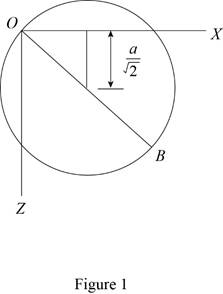
Refer Figure 1.
Refer Figure 9.28.
Apply parallel axis theorem
Show the moment of inertia of the circular cylinder about the y axis as follows:
Show the moment of inertia of the circular cylinder about the x and z axis as follows:
Here, a is the radius of the cylinder and L is the length of the cylinder.
Substitute
The centroidal axis products of inertia are zero due to symmetry.
Write the centroidal locations as measured from the origin O along the x, y and z axis as below;
Express the moment of inertia
Express the moment of inertia
Express the moment of inertia
Show the Equation 9.56 as follows:
Substitute
Substitute
Solve the above Equation and get the values of
Show the principal moment of inertia as follows:
Thus, the principal mass moment of inertia are
(b)
Find the angles made by the principal axis of inertia at O with the coordinate axis.
(b)
Answer to Problem 9.179P
The angles made by the principal axis of inertia at O with the coordinate axis is
Explanation of Solution
Given information:
Consider the direction cosines of each principal axis are denoted by
Calculation:
Refer Part (a).
Show the Equation 9.54 as follows:
Substitute
Modify Equation (3).
Consider
Solve Equation (4).
Add both the Equation in Equation (4).
Substitute
Show the Equation 9.57 as follows:
Substitute
Consider K1.
Substitute
Calculate the value of
Substitute
Show the direction cosines
Conisder K3.
Substitute
Calculate the value of
Substitute
Show the direction cosines
Consider K2.
Show the Equation 9.54b as follows:
Substitute
Refer Equation (3) and (6).
Substitute
Modify above Equations as follows:
Solve Equation (8) and get the value of
Show the Equation 9.57 as follows:
Substitute
Show the direction cosines
Thus, the velocity of the point B is
(c)
Sketch the body and show the orientation of the principal axis of inertia relative to x, y, and z axis.
(c)
Explanation of Solution
Given information:
Calculation:
Refer Part (a) and (b).
Sketch the body and show the orientation of the principal axis of inertia relative to x, y, and z axis as shown in Figure 2.
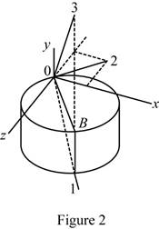
Refer Figure 2.
The principal axis 1 and 3 lies on the vertical plane of symmetry passing through OB.
The principal axis 2 lies in xz plane.
Want to see more full solutions like this?
Chapter 9 Solutions
Vector Mechanics for Engineers: Statics


- A 10-kg box is pulled along P,Na rough surface by a force P, as shown in thefigure. The pulling force linearly increaseswith time, while the particle is motionless att = 0s untilit reaches a maximum force of100 Nattimet = 4s. If the ground has staticand kinetic friction coefficients of u, = 0.6 andHU, = 0.4 respectively, determine the velocityof the A 1 0 - kg box is pulled along P , N a rough surface by a force P , as shown in the figure. The pulling force linearly increases with time, while the particle is motionless at t = 0 s untilit reaches a maximum force of 1 0 0 Nattimet = 4 s . If the ground has static and kinetic friction coefficients of u , = 0 . 6 and HU , = 0 . 4 respectively, determine the velocity of the particle att = 4 s .arrow_forwardCalculate the speed of the driven member with the following conditions: Diameter of the motor pulley: 4 in Diameter of the driven pulley: 12 in Speed of the motor pulley: 1800 rpmarrow_forward4. In the figure, shaft A made of AISI 1010 hot-rolled steel, is welded to a fixed support and is subjected to loading by equal and opposite Forces F via shaft B. Stress concentration factors K₁ (1.7) and Kts (1.6) are induced by the 3mm fillet. Notch sensitivities are q₁=0.9 and qts=1. The length of shaft A from the fixed support to the connection at shaft B is 1m. The load F cycles from 0.5 to 2kN and a static load P is 100N. For shaft A, find the factor of safety (for infinite life) using the modified Goodman fatigue failure criterion. 3 mm fillet Shaft A 20 mm 25 mm Shaft B 25 mmarrow_forward
- Please sovle this for me and please don't use aiarrow_forwardPlease sovle this for me and please don't use aiarrow_forward3. The cold-drawn AISI 1040 steel bar shown in the figure is subjected to a completely reversed axial load fluctuating between 28 kN in compression to 28 kN in tension. Estimate the fatigue factor of safety based on achieving infinite life (using Goodman line) and the yielding factor of safety. If infinite life is not predicted, estimate the number of cycles to failure. 25 mm + 6-mm D. 10 mmarrow_forward
- CORRECT AND DETAILED SOLUTION WITH FBD ONLY. I WILL UPVOTE 1. The truss shown is supported by hinge at A and cable at E.Given: H = 4m, S = 1.5 m, α = 75⁰, θ = 33⁰.Allowable tensile stress in cable = 64 MPa.Allowable compressive stress in all members = 120 MPaAllowable tensile stress in all members = 180 MPa1.Calculate the maximum permissible P, in kN, if the diameter of the cable is 20 mm.2.If P = 40 kN, calculate the required area (mm2) of member BC.3. If members have solid square section, with dimension 15 mm, calculate the maximum permissible P (kN) based on the allowable strength of member HI.ANSWERS: (1) 45.6 kN; (2) 83.71 mm2; (3) 171.76 kNarrow_forwardCORRECT AND DETAILED SOLUTION WITH FBD ONLY. I WILL UPVOTE 2: A wire 4 meters long is stretched horizontally between points 4 meters apart. The wire is 25 mm2 in cross-section with a modulus of elasticity of 200 GPa. A load W placed at the center of the wire produces a sag Δ.1.Calculate the tension (N) in the wire if sag Δ = 30 mm.2.Calculate the magnitude of W, in N, if sag Δ = 54.3 mm.3. If W is 60 N, what is the sag (in mm)?ANSWERS: (1) 562 N, (2) 100 N, (3) 45.8 Narrow_forwardCORRECT AND DETAILED SOLUTION WITH FBD ONLY. I WILL UPVOTE 4 : A cable and pulley system at D is used to bring a 230-kg pole (ACB) to a vertical position as shown. The cable has tensile force T and is attached at C. The length of the pole is 6.0 m, the outer diameter is d = 140 mm, and the wall thickness t = 12 mm. The pole pivots about a pin at A. The allowable shear stress in the pin is 60 MPa and the allowable bearing stress is 90 MPa. The diameter of the cable is 8 mm.1.Find the minimum diameter (mm) of the pin at A to support the weight of the pole in the position shown.2.Calculate the elongation (mm) of the cable CD.3.Calculate the vertical displacement of point C, in mm.ANSWERS: (1) 6 mm, (2) 1.186 mm, (3) 1.337 mm--arrow_forward
 International Edition---engineering Mechanics: St...Mechanical EngineeringISBN:9781305501607Author:Andrew Pytel And Jaan KiusalaasPublisher:CENGAGE L