
Vector Mechanics for Engineers: Statics
12th Edition
ISBN: 9781259977268
Author: Ferdinand P. Beer, E. Russell Johnston Jr., David Mazurek
Publisher: McGraw-Hill Education
expand_more
expand_more
format_list_bulleted
Concept explainers
Videos
Textbook Question
Chapter 9.3, Problem 9.76P
9.75 through 9.78 Using the parallel-axis theorem, determine the product of inertia of the area shown with respect to the centroidal x and y axes.
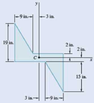
Fig. P9.76
Expert Solution & Answer
Want to see the full answer?
Check out a sample textbook solution
Students have asked these similar questions
Problem (17): water flowing in an open channel of a rectangular cross-section with width (b) transitions from a
mild slope to a steep slope (i.e., from subcritical to supercritical flow) with normal water depths of (y₁) and
(y2), respectively.
Given the values of y₁ [m], y₂ [m], and b [m], calculate the discharge in the channel (Q) in [Lit/s].
Givens:
y1 = 4.112 m
y2 =
0.387 m
b = 0.942 m
Answers:
( 1 ) 1880.186 lit/s
( 2 ) 4042.945 lit/s
( 3 ) 2553.11 lit/s
( 4 ) 3130.448 lit/s
Problem (14): A pump is being used to lift water from an underground
tank through a pipe of diameter (d) at discharge (Q). The total head
loss until the pump entrance can be calculated as (h₁ = K[V²/2g]), h
where (V) is the flow velocity in the pipe. The elevation difference
between the pump and tank surface is (h).
Given the values of h [cm], d [cm], and K [-], calculate the maximum
discharge Q [Lit/s] beyond which cavitation would take place at the
pump entrance. Assume Turbulent flow conditions.
Givens:
h = 120.31 cm
d = 14.455 cm
K = 8.976
Q
Answers:
(1) 94.917 lit/s
(2) 49.048 lit/s
( 3 ) 80.722 lit/s
68.588 lit/s
4
Problem (13): A pump is being used to lift water from the bottom
tank to the top tank in a galvanized iron pipe at a discharge (Q).
The length and diameter of the pipe section from the bottom tank
to the pump are (L₁) and (d₁), respectively. The length and
diameter of the pipe section from the pump to the top tank are
(L2) and (d2), respectively.
Given the values of Q [L/s], L₁ [m], d₁ [m], L₂ [m], d₂ [m],
calculate total head loss due to friction (i.e., major loss) in the
pipe (hmajor-loss) in [cm].
Givens:
L₁,d₁
Pump
L₂,d2
오
0.533 lit/s
L1 =
6920.729 m
d1 =
1.065 m
L2 =
70.946 m
d2
0.072 m
Answers:
(1)
3.069 cm
(2) 3.914 cm
( 3 ) 2.519 cm
( 4 ) 1.855 cm
TABLE 8.1
Equivalent Roughness for New Pipes
Pipe
Riveted steel
Concrete
Wood stave
Cast iron
Galvanized iron
Equivalent Roughness, &
Feet
Millimeters
0.003-0.03 0.9-9.0
0.001-0.01 0.3-3.0
0.0006-0.003 0.18-0.9
0.00085
0.26
0.0005
0.15
0.045
0.000005
0.0015
0.0 (smooth) 0.0 (smooth)
Commercial steel or wrought iron 0.00015
Drawn…
Chapter 9 Solutions
Vector Mechanics for Engineers: Statics
Ch. 9.1 - 9.1 through 9.4 Determine by direct integration...Ch. 9.1 - 9.1 through 9.4 Determine by direct integration...Ch. 9.1 - 9.1 through 9.4 Determine by direct integration...Ch. 9.1 - 9.1 through 9.4 Determine by direct integration...Ch. 9.1 - 9.5 through 9.8 Determine by direct integration...Ch. 9.1 - 9.5 through 9.8 Determine by direct integration...Ch. 9.1 - 9.5 through 9.8 Determine by direct integration...Ch. 9.1 - 9.5 through 9.8 Determine by direct integration...Ch. 9.1 - 9.9 through 9.11 Determine by direct integration...Ch. 9.1 - 9.9 through 9.11 Determine by direct integration...
Ch. 9.1 - 9.9 through 9.11 Determine by direct integration...Ch. 9.1 - 9.12 through 9.14 Determine by direct integration...Ch. 9.1 - Prob. 9.13PCh. 9.1 - 9.12 through 9.14 Determine by direct integration...Ch. 9.1 - 9.15 and 9.16 Determine the moment of inertia and...Ch. 9.1 - Prob. 9.16PCh. 9.1 - 9.17 and 9.18 Determine the moment of inertia and...Ch. 9.1 - Prob. 9.18PCh. 9.1 - Determine the moment of inertia and the radius of...Ch. 9.1 - Prob. 9.20PCh. 9.1 - Prob. 9.21PCh. 9.1 - Determine the polar moment of inertia and the...Ch. 9.1 - 9.23 and 9.24 Determine the polar moment of...Ch. 9.1 - 9.23 and 9.24 Determine the polar moment of...Ch. 9.1 - (a) Determine by direct integration the polar...Ch. 9.1 - (a) Show that the polar radius of gyration kQ of...Ch. 9.1 - Determine the polar moment of inertia and the...Ch. 9.1 - Determine the polar moment of inertia and the...Ch. 9.1 - Using the polar moment of inertia of the isosceles...Ch. 9.1 - Prove that the centroidal polar moment of inertia...Ch. 9.2 - 9.31 and 9.32 Determine the moment of inertia and...Ch. 9.2 - 9.31 and 9.32 Determine the moment of inertia and...Ch. 9.2 - 9.33 and 9.34 Determine the moment of inertia and...Ch. 9.2 - 9.33 and 9.34 Determine the moment of inertia and...Ch. 9.2 - Prob. 9.35PCh. 9.2 - Determine the moments of inertia of the shaded...Ch. 9.2 - Prob. 9.37PCh. 9.2 - Fig. P9.37 and P9.38 9.38 Knowing that the shaded...Ch. 9.2 - Prob. 9.39PCh. 9.2 - Fig. P9.39 and P9.40 9.40 The polar moments of...Ch. 9.2 - Prob. 9.41PCh. 9.2 - 9.41 through 9.44 Determine the moments of inertia...Ch. 9.2 - 9.41 through 9.44 Determine the moments of inertia...Ch. 9.2 - 9.41 through 9.44 Determine the moments of inertia...Ch. 9.2 - 9.45 and 9.46 Determine the polar moment of...Ch. 9.2 - 9.45 and 9.46 Determine the polar moment of...Ch. 9.2 - Prob. 9.47PCh. 9.2 - Prob. 9.48PCh. 9.2 - Prob. 9.49PCh. 9.2 - Prob. 9.50PCh. 9.2 - Four L3 3 14 - in. angles are welded to a rolled...Ch. 9.2 - Two 20-mm steel plates are welded to a rolled S...Ch. 9.2 - A channel and a plate are welded together as shown...Ch. 9.2 - The strength of the rolled W section shown is...Ch. 9.2 - Two L76 76 6.4-mm angles are welded to a C250 ...Ch. 9.2 - Two steel plates are welded to a rolled W section...Ch. 9.2 - 9.57 and 9.58 The panel shown forms the end of a...Ch. 9.2 - 9.57 and 9.58 The panel shown forms the end of a...Ch. 9.2 - 9.59 and 9.60 The panel shown forms the end of a...Ch. 9.2 - 9.59 and 9.60 The panel shown forms the end of a...Ch. 9.2 - A vertical trapezoidal gate that is used as an...Ch. 9.2 - The cover for a 0.5-m-diameter access hole in a...Ch. 9.2 - Determine the x coordinate of the centroid of the...Ch. 9.2 - Determine the x coordinate of the centroid of the...Ch. 9.2 - Show that the system of hydrostatic forces acting...Ch. 9.2 - Show that the resultant of the hydrostatic forces...Ch. 9.3 - 9.67 through 9.70 Determine by direct integration...Ch. 9.3 - 9.67 through 9.70 Determine by direct integration...Ch. 9.3 - 9.67 through 9.70 Determine by direct integration...Ch. 9.3 - Prob. 9.70PCh. 9.3 - 9.71 through 9.74 Using the parallel-axis theorem,...Ch. 9.3 - 9.71 through 9.74 Using the parallel-axis theorem,...Ch. 9.3 - 9.71 through 9.74 Using the parallel-axis theorem,...Ch. 9.3 - Prob. 9.74PCh. 9.3 - 9.75 through 9.78 Using the parallel-axis theorem,...Ch. 9.3 - 9.75 through 9.78 Using the parallel-axis theorem,...Ch. 9.3 - 9.75 through 9.78 Using the parallel-axis theorem,...Ch. 9.3 - Prob. 9.78PCh. 9.3 - Determine for the quarter ellipse of Prob. 9.67...Ch. 9.3 - Determine the moments of inertia and the product...Ch. 9.3 - Determine the moments of inertia and the product...Ch. 9.3 - 9.75 through 9.78 Using the parallel-axis theorem,...Ch. 9.3 - Determine the moments of inertia and the product...Ch. 9.3 - Determine the moments of inertia and the product...Ch. 9.3 - Prob. 9.85PCh. 9.3 - 9.86 through 9.88 For the area indicated,...Ch. 9.3 - 9.86 through 9.88 For the area indicated,...Ch. 9.3 - 9.86 through 9.88 For the area indicated,...Ch. 9.3 - 9.89 and 9.90 For the angle cross section...Ch. 9.3 - 9.89 and 9.90 For the angle cross section...Ch. 9.4 - Using Mohrs circle, determine for the quarter...Ch. 9.4 - Using Mohrs circle, determine the moments of...Ch. 9.4 - Using Mohrs circle, determine the moments of...Ch. 9.4 - Using Mohrs circle, determine the moments of...Ch. 9.4 - Using Mohrs circle, determine the moments of...Ch. 9.4 - Using Mohrs circle, determine the moments of...Ch. 9.4 - For the quarter ellipse of Prob. 9.67, use Mohrs...Ch. 9.4 - Prob. 9.98PCh. 9.4 - 9.98 though 9.102 Using Mohrs circle, determine...Ch. 9.4 - 9.98 though 9.102 Using Mohrs circle, determine...Ch. 9.4 - 9.98 through 9.102 Using Mohrs circle, determine...Ch. 9.4 - 9.98 through 9.102 Using Mohrs circle, determine...Ch. 9.4 - Prob. 9.103PCh. 9.4 - 9.104 and 9.105 Using Mohrs circle, determine the...Ch. 9.4 - 9.104 and 9.105 Using Mohrs circle, determine the...Ch. 9.4 - Prob. 9.106PCh. 9.4 - it is known that for a given area Iy = 48 106 mm4...Ch. 9.4 - Prob. 9.108PCh. 9.4 - Using Mohrs circle, prove that the expression...Ch. 9.4 - Using the invariance property established in the...Ch. 9.5 - A thin plate with a mass m is cut in the shape of...Ch. 9.5 - A ring with a mass m is cut from a thin uniform...Ch. 9.5 - Prob. 9.113PCh. 9.5 - The parabolic spandrel shown was cut from a thin,...Ch. 9.5 - Prob. 9.115PCh. 9.5 - Fig. P9.115 and P9.116 9.116 A piece of thin,...Ch. 9.5 - A thin plate of mass m is cut in the shape of an...Ch. 9.5 - Prob. 9.118PCh. 9.5 - Prob. 9.119PCh. 9.5 - The area shown is revolved about the x axis to...Ch. 9.5 - Prob. 9.121PCh. 9.5 - Determine by direct integration the mass moment of...Ch. 9.5 - Fig. P9.122 and P9.123 9.123 Determine by direct...Ch. 9.5 - Determine by direct integration the mass moment of...Ch. 9.5 - Prob. 9.125PCh. 9.5 - A thin steel wire is bent into the shape shown....Ch. 9.5 - Shown is the cross section of an idler roller....Ch. 9.5 - Shown is the cross section of a molded flat-belt...Ch. 9.5 - Prob. 9.129PCh. 9.5 - Knowing that the thin cylindrical shell shown has...Ch. 9.5 - A circular hole of radius r is to be drilled...Ch. 9.5 - Prob. 9.132PCh. 9.5 - After a period of use, one of the blades of a...Ch. 9.5 - Determine the mass moment of inertia of the 0.9-lb...Ch. 9.5 - 9.135 and 9.136 A 2-mm thick piece of sheet steel...Ch. 9.5 - 9.135 and 9.136 A 2 -mm thick piece of sheet steel...Ch. 9.5 - Prob. 9.137PCh. 9.5 - A section of sheet steel 0.03 in. thick is cut and...Ch. 9.5 - Prob. 9.139PCh. 9.5 - Prob. 9.140PCh. 9.5 - The machine element shown is fabricated from...Ch. 9.5 - Determine the mass moments of inertia and the...Ch. 9.5 - Determine the mass moment of inertia of the steel...Ch. 9.5 - Fig. P9.143 and P9.144 9.144 Determine the mass...Ch. 9.5 - Determine the mass moment of inertia of the steel...Ch. 9.5 - Aluminum wire with a weight per unit length of...Ch. 9.5 - The figure shown is formed of 18-in.-diameter...Ch. 9.5 - A homogeneous wire with a mass per unit length of...Ch. 9.6 - Determine the mass products of inertia Ixy, Iyz,...Ch. 9.6 - Determine the mass products of inertia Ixy, Iyz,...Ch. 9.6 - Determine the mass products of inertia Ixy, Iyz,...Ch. 9.6 - Determine the mass products of inertia Ixy, Iyz,...Ch. 9.6 - Prob. 9.153PCh. 9.6 - Prob. 9.154PCh. 9.6 - 9.153 through 9.156 A section of sheet steel 2 mm...Ch. 9.6 - 9.153 through 9.156 A section of sheet steel 2 mm...Ch. 9.6 - The figure shown is formed of 1.5-mm-diameter...Ch. 9.6 - Prob. 9.158PCh. 9.6 - 9.159 and 9.160 Brass wire with a weight per unit...Ch. 9.6 - Fig. P9.160 9.159 and 9.160 Brass wire with a...Ch. 9.6 - Complete the derivation of Eqs. (9.47) that...Ch. 9.6 - Prob. 9.162PCh. 9.6 - Prob. 9.163PCh. 9.6 - Prob. 9.164PCh. 9.6 - Shown is the machine element of Prob. 9.141....Ch. 9.6 - Determine the mass moment of inertia of the steel...Ch. 9.6 - The thin, bent plate shown is of uniform density...Ch. 9.6 - A piece of sheet steel with thickness t and...Ch. 9.6 - Determine the mass moment of inertia of the...Ch. 9.6 - 9.170 through 9.172 For the wire figure of the...Ch. 9.6 - Prob. 9.171PCh. 9.6 - 9.172 Prob. 9.146 9.146 Aluminum wire with a...Ch. 9.6 - For the homogeneous circular cylinder shown with...Ch. 9.6 - For the rectangular prism shown, determine the...Ch. 9.6 - Prob. 9.175PCh. 9.6 - Prob. 9.176PCh. 9.6 - Consider a cube with mass m and side a. (a) Show...Ch. 9.6 - Prob. 9.178PCh. 9.6 - Prob. 9.179PCh. 9.6 - 9.180 through 9.184 For the component described in...Ch. 9.6 - 9.180 through 9.184 For the component described in...Ch. 9.6 - Prob. 9.182PCh. 9.6 - 9.180 through 9.184 For the component described in...Ch. 9.6 - 9.180 through 9.184 For the component described in...Ch. 9 - Determine by direct integration the moments of...Ch. 9 - Determine the moment of inertia and the radius of...Ch. 9 - Determine the moment of inertia and the radius of...Ch. 9 - Determine the moments of inertia Ix and Iy of the...Ch. 9 - Determine the polar moment of inertia of the area...Ch. 9 - Two L4 4 12-in. angles are welded to a steel...Ch. 9 - Using the parallel-axis theorem, determine the...Ch. 9 - Prob. 9.192RPCh. 9 - Fig. P9.193 and P9.194 9.193 A thin plate with a...Ch. 9 - Fig. P9.193 and P9.194 9.194 A thin plate with...Ch. 9 - A 2-mm-thick piece of sheet steel is cut and bent...Ch. 9 - Determine the mass moment of inertia of the steel...
Knowledge Booster


Learn more about
Need a deep-dive on the concept behind this application? Look no further. Learn more about this topic, mechanical-engineering and related others by exploring similar questions and additional content below.Similar questions
- The flow rate is 12.275 Liters/s and the diameter is 6.266 cm.arrow_forwardAn experimental setup is being built to study the flow in a large water main (i.e., a large pipe). The water main is expected to convey a discharge (Qp). The experimental tube will be built at a length scale of 1/20 of the actual water main. After building the experimental setup, the pressure drop per unit length in the model tube (APm/Lm) is measured. Problem (20): Given the value of APm/Lm [kPa/m], and assuming pressure coefficient similitude, calculate the drop in the pressure per unit length of the water main (APP/Lp) in [Pa/m]. Givens: AP M/L m = 590.637 kPa/m meen Answers: ( 1 ) 59.369 Pa/m ( 2 ) 73.83 Pa/m (3) 95.443 Pa/m ( 4 ) 44.444 Pa/m *******arrow_forwardFind the reaction force in y if Ain = 0.169 m^2, Aout = 0.143 m^2, p_in = 0.552 atm, Q = 0.367 m^3/s, α = 31.72 degrees. The pipe is flat on the ground so do not factor in weight of the pipe and fluid.arrow_forward
- Find the reaction force in x if Ain = 0.301 m^2, Aout = 0.177 m^2, p_in = 1.338 atm, Q = 0.669 m^3/s, and α = 37.183 degreesarrow_forwardProblem 5: Three-Force Equilibrium A structural connection at point O is in equilibrium under the action of three forces. • • . Member A applies a force of 9 kN vertically upward along the y-axis. Member B applies an unknown force F at the angle shown. Member C applies an unknown force T along its length at an angle shown. Determine the magnitudes of forces F and T required for equilibrium, assuming 0 = 90° y 9 kN Aarrow_forwardProblem 19: Determine the force in members HG, HE, and DE of the truss, and state if the members are in tension or compression. 4 ft K J I H G B C D E F -3 ft -3 ft 3 ft 3 ft 3 ft- 1500 lb 1500 lb 1500 lb 1500 lb 1500 lbarrow_forward
- Problem 14: Determine the reactions at the pin A, and the tension in cord. Neglect the thickness of the beam. F1=26kN F2 13 12 80° -2m 3marrow_forwardProblem 22: Determine the force in members GF, FC, and CD of the bridge truss and state if the members are in tension or compression. F 15 ft B D -40 ft 40 ft -40 ft 40 ft- 5 k 10 k 15 k 30 ft Earrow_forwardProblem 20: Determine the force in members BC, HC, and HG. After the truss is sectioned use a single equation of equilibrium for the calculation of each force. State if the members are in tension or compression. 5 kN 4 kN 4 kN 3 kN 2 kN B D E F 3 m -5 m- -5 m- 5 m 5 m-arrow_forward
- An experimental setup is being built to study the flow in a large water main (i.e., a large pipe). The water main is expected to convey a discharge (Qp). The experimental tube will be built at a length scale of 1/20 of the actual water main. After building the experimental setup, the pressure drop per unit length in the model tube (APm/Lm) is measured. Problem (19): Given the value of Qp [m³/s], and assuming Reynolds number similitude between the water main and experimental tube, calculate the flow rate in the model tube (Qm) in [lit/s]. = 30.015 m^3/sarrow_forwardProblem 11: The lamp has a weight of 15 lb and is supported by the six cords connected together as shown. Determine the tension in each cord and the angle 0 for equilibrium. Cord BC is horizontal. E 30° B 60° Aarrow_forwardProblem 10: If the bucket weighs 50 lb, determine the tension developed in each of the wires. B $30° 5 E D 130°arrow_forward
arrow_back_ios
SEE MORE QUESTIONS
arrow_forward_ios
Recommended textbooks for you
 Elements Of ElectromagneticsMechanical EngineeringISBN:9780190698614Author:Sadiku, Matthew N. O.Publisher:Oxford University Press
 Mechanics of Materials (10th Edition)Mechanical EngineeringISBN:9780134319650Author:Russell C. HibbelerPublisher:PEARSON
 Thermodynamics: An Engineering ApproachMechanical EngineeringISBN:9781259822674Author:Yunus A. Cengel Dr., Michael A. BolesPublisher:McGraw-Hill Education
 Control Systems EngineeringMechanical EngineeringISBN:9781118170519Author:Norman S. NisePublisher:WILEY
 Mechanics of Materials (MindTap Course List)Mechanical EngineeringISBN:9781337093347Author:Barry J. Goodno, James M. GerePublisher:Cengage Learning
 Engineering Mechanics: StaticsMechanical EngineeringISBN:9781118807330Author:James L. Meriam, L. G. Kraige, J. N. BoltonPublisher:WILEY
Elements Of Electromagnetics
Mechanical Engineering
ISBN:9780190698614
Author:Sadiku, Matthew N. O.
Publisher:Oxford University Press
Mechanics of Materials (10th Edition)
Mechanical Engineering
ISBN:9780134319650
Author:Russell C. Hibbeler
Publisher:PEARSON
Thermodynamics: An Engineering Approach
Mechanical Engineering
ISBN:9781259822674
Author:Yunus A. Cengel Dr., Michael A. Boles
Publisher:McGraw-Hill Education
Control Systems Engineering
Mechanical Engineering
ISBN:9781118170519
Author:Norman S. Nise
Publisher:WILEY
Mechanics of Materials (MindTap Course List)
Mechanical Engineering
ISBN:9781337093347
Author:Barry J. Goodno, James M. Gere
Publisher:Cengage Learning
Engineering Mechanics: Statics
Mechanical Engineering
ISBN:9781118807330
Author:James L. Meriam, L. G. Kraige, J. N. Bolton
Publisher:WILEY
moment of inertia; Author: NCERT OFFICIAL;https://www.youtube.com/watch?v=A4KhJYrt4-s;License: Standard YouTube License, CC-BY