
Vector Mechanics for Engineers: Statics
12th Edition
ISBN: 9781259977268
Author: Ferdinand P. Beer, E. Russell Johnston Jr., David Mazurek
Publisher: McGraw-Hill Education
expand_more
expand_more
format_list_bulleted
Concept explainers
Videos
Textbook Question
Chapter 9.3, Problem 9.75P
9.75 through 9.78 Using the parallel-axis theorem, determine the product of inertia of the area shown with respect to the centroidal x and y axes.
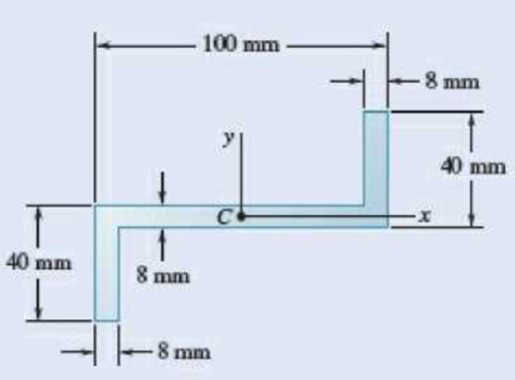
Fig. P9.75
Expert Solution & Answer
Want to see the full answer?
Check out a sample textbook solution
Students have asked these similar questions
Calculate the force in cable AB and the angle θ for the support system shown. Round your final answers to two decimal places.
1.53 In the steel structure shown, a 6-mm-diameter pin is used at C and
10-mm-diameter pins are used at B and D. The ultimate shearing
stress is 150 MPa at all connections, and the ultimate normal stress
is 400 MPa in link BD. Knowing that a factor of safety of 3.0 is
desired, determine the largest load P that can be applied at A. Note
that link BD is not reinforced around the pin holes.
Front view
D
D
6 mm
18 mm
B
A
B
Side view
160 mm
120 mm
A
B
Top view
CORRECT AND DETAILED HANDWRITTEN SOLUTION WITH FBD ONLY. I WILL UPVOTE THANK YOU. CORRECT ANSWER IS ALREADY PROVIDED.
16: Determine (a) the maximum bending stress, (b)the maximum shearing stress, (c) compressive bending stress atthe roller support, and (d) the shearing stress 1 in below the topsurface of the beam at the location 1 ft to the right of the rollersupport in the simply supported beam shown in Fig. 8-70.ANS: (a) 21,945.313 lb/in2; (b) 1656.25 lb/in2; (c) 10,000 lb/in2; (d) 190.972 lb/in2
Chapter 9 Solutions
Vector Mechanics for Engineers: Statics
Ch. 9.1 - 9.1 through 9.4 Determine by direct integration...Ch. 9.1 - 9.1 through 9.4 Determine by direct integration...Ch. 9.1 - 9.1 through 9.4 Determine by direct integration...Ch. 9.1 - 9.1 through 9.4 Determine by direct integration...Ch. 9.1 - 9.5 through 9.8 Determine by direct integration...Ch. 9.1 - 9.5 through 9.8 Determine by direct integration...Ch. 9.1 - 9.5 through 9.8 Determine by direct integration...Ch. 9.1 - 9.5 through 9.8 Determine by direct integration...Ch. 9.1 - 9.9 through 9.11 Determine by direct integration...Ch. 9.1 - 9.9 through 9.11 Determine by direct integration...
Ch. 9.1 - 9.9 through 9.11 Determine by direct integration...Ch. 9.1 - 9.12 through 9.14 Determine by direct integration...Ch. 9.1 - Prob. 9.13PCh. 9.1 - 9.12 through 9.14 Determine by direct integration...Ch. 9.1 - 9.15 and 9.16 Determine the moment of inertia and...Ch. 9.1 - Prob. 9.16PCh. 9.1 - 9.17 and 9.18 Determine the moment of inertia and...Ch. 9.1 - Prob. 9.18PCh. 9.1 - Determine the moment of inertia and the radius of...Ch. 9.1 - Prob. 9.20PCh. 9.1 - Prob. 9.21PCh. 9.1 - Determine the polar moment of inertia and the...Ch. 9.1 - 9.23 and 9.24 Determine the polar moment of...Ch. 9.1 - 9.23 and 9.24 Determine the polar moment of...Ch. 9.1 - (a) Determine by direct integration the polar...Ch. 9.1 - (a) Show that the polar radius of gyration kQ of...Ch. 9.1 - Determine the polar moment of inertia and the...Ch. 9.1 - Determine the polar moment of inertia and the...Ch. 9.1 - Using the polar moment of inertia of the isosceles...Ch. 9.1 - Prove that the centroidal polar moment of inertia...Ch. 9.2 - 9.31 and 9.32 Determine the moment of inertia and...Ch. 9.2 - 9.31 and 9.32 Determine the moment of inertia and...Ch. 9.2 - 9.33 and 9.34 Determine the moment of inertia and...Ch. 9.2 - 9.33 and 9.34 Determine the moment of inertia and...Ch. 9.2 - Prob. 9.35PCh. 9.2 - Determine the moments of inertia of the shaded...Ch. 9.2 - Prob. 9.37PCh. 9.2 - Fig. P9.37 and P9.38 9.38 Knowing that the shaded...Ch. 9.2 - Prob. 9.39PCh. 9.2 - Fig. P9.39 and P9.40 9.40 The polar moments of...Ch. 9.2 - Prob. 9.41PCh. 9.2 - 9.41 through 9.44 Determine the moments of inertia...Ch. 9.2 - 9.41 through 9.44 Determine the moments of inertia...Ch. 9.2 - 9.41 through 9.44 Determine the moments of inertia...Ch. 9.2 - 9.45 and 9.46 Determine the polar moment of...Ch. 9.2 - 9.45 and 9.46 Determine the polar moment of...Ch. 9.2 - Prob. 9.47PCh. 9.2 - Prob. 9.48PCh. 9.2 - Prob. 9.49PCh. 9.2 - Prob. 9.50PCh. 9.2 - Four L3 3 14 - in. angles are welded to a rolled...Ch. 9.2 - Two 20-mm steel plates are welded to a rolled S...Ch. 9.2 - A channel and a plate are welded together as shown...Ch. 9.2 - The strength of the rolled W section shown is...Ch. 9.2 - Two L76 76 6.4-mm angles are welded to a C250 ...Ch. 9.2 - Two steel plates are welded to a rolled W section...Ch. 9.2 - 9.57 and 9.58 The panel shown forms the end of a...Ch. 9.2 - 9.57 and 9.58 The panel shown forms the end of a...Ch. 9.2 - 9.59 and 9.60 The panel shown forms the end of a...Ch. 9.2 - 9.59 and 9.60 The panel shown forms the end of a...Ch. 9.2 - A vertical trapezoidal gate that is used as an...Ch. 9.2 - The cover for a 0.5-m-diameter access hole in a...Ch. 9.2 - Determine the x coordinate of the centroid of the...Ch. 9.2 - Determine the x coordinate of the centroid of the...Ch. 9.2 - Show that the system of hydrostatic forces acting...Ch. 9.2 - Show that the resultant of the hydrostatic forces...Ch. 9.3 - 9.67 through 9.70 Determine by direct integration...Ch. 9.3 - 9.67 through 9.70 Determine by direct integration...Ch. 9.3 - 9.67 through 9.70 Determine by direct integration...Ch. 9.3 - Prob. 9.70PCh. 9.3 - 9.71 through 9.74 Using the parallel-axis theorem,...Ch. 9.3 - 9.71 through 9.74 Using the parallel-axis theorem,...Ch. 9.3 - 9.71 through 9.74 Using the parallel-axis theorem,...Ch. 9.3 - Prob. 9.74PCh. 9.3 - 9.75 through 9.78 Using the parallel-axis theorem,...Ch. 9.3 - 9.75 through 9.78 Using the parallel-axis theorem,...Ch. 9.3 - 9.75 through 9.78 Using the parallel-axis theorem,...Ch. 9.3 - Prob. 9.78PCh. 9.3 - Determine for the quarter ellipse of Prob. 9.67...Ch. 9.3 - Determine the moments of inertia and the product...Ch. 9.3 - Determine the moments of inertia and the product...Ch. 9.3 - 9.75 through 9.78 Using the parallel-axis theorem,...Ch. 9.3 - Determine the moments of inertia and the product...Ch. 9.3 - Determine the moments of inertia and the product...Ch. 9.3 - Prob. 9.85PCh. 9.3 - 9.86 through 9.88 For the area indicated,...Ch. 9.3 - 9.86 through 9.88 For the area indicated,...Ch. 9.3 - 9.86 through 9.88 For the area indicated,...Ch. 9.3 - 9.89 and 9.90 For the angle cross section...Ch. 9.3 - 9.89 and 9.90 For the angle cross section...Ch. 9.4 - Using Mohrs circle, determine for the quarter...Ch. 9.4 - Using Mohrs circle, determine the moments of...Ch. 9.4 - Using Mohrs circle, determine the moments of...Ch. 9.4 - Using Mohrs circle, determine the moments of...Ch. 9.4 - Using Mohrs circle, determine the moments of...Ch. 9.4 - Using Mohrs circle, determine the moments of...Ch. 9.4 - For the quarter ellipse of Prob. 9.67, use Mohrs...Ch. 9.4 - Prob. 9.98PCh. 9.4 - 9.98 though 9.102 Using Mohrs circle, determine...Ch. 9.4 - 9.98 though 9.102 Using Mohrs circle, determine...Ch. 9.4 - 9.98 through 9.102 Using Mohrs circle, determine...Ch. 9.4 - 9.98 through 9.102 Using Mohrs circle, determine...Ch. 9.4 - Prob. 9.103PCh. 9.4 - 9.104 and 9.105 Using Mohrs circle, determine the...Ch. 9.4 - 9.104 and 9.105 Using Mohrs circle, determine the...Ch. 9.4 - Prob. 9.106PCh. 9.4 - it is known that for a given area Iy = 48 106 mm4...Ch. 9.4 - Prob. 9.108PCh. 9.4 - Using Mohrs circle, prove that the expression...Ch. 9.4 - Using the invariance property established in the...Ch. 9.5 - A thin plate with a mass m is cut in the shape of...Ch. 9.5 - A ring with a mass m is cut from a thin uniform...Ch. 9.5 - Prob. 9.113PCh. 9.5 - The parabolic spandrel shown was cut from a thin,...Ch. 9.5 - Prob. 9.115PCh. 9.5 - Fig. P9.115 and P9.116 9.116 A piece of thin,...Ch. 9.5 - A thin plate of mass m is cut in the shape of an...Ch. 9.5 - Prob. 9.118PCh. 9.5 - Prob. 9.119PCh. 9.5 - The area shown is revolved about the x axis to...Ch. 9.5 - Prob. 9.121PCh. 9.5 - Determine by direct integration the mass moment of...Ch. 9.5 - Fig. P9.122 and P9.123 9.123 Determine by direct...Ch. 9.5 - Determine by direct integration the mass moment of...Ch. 9.5 - Prob. 9.125PCh. 9.5 - A thin steel wire is bent into the shape shown....Ch. 9.5 - Shown is the cross section of an idler roller....Ch. 9.5 - Shown is the cross section of a molded flat-belt...Ch. 9.5 - Prob. 9.129PCh. 9.5 - Knowing that the thin cylindrical shell shown has...Ch. 9.5 - A circular hole of radius r is to be drilled...Ch. 9.5 - Prob. 9.132PCh. 9.5 - After a period of use, one of the blades of a...Ch. 9.5 - Determine the mass moment of inertia of the 0.9-lb...Ch. 9.5 - 9.135 and 9.136 A 2-mm thick piece of sheet steel...Ch. 9.5 - 9.135 and 9.136 A 2 -mm thick piece of sheet steel...Ch. 9.5 - Prob. 9.137PCh. 9.5 - A section of sheet steel 0.03 in. thick is cut and...Ch. 9.5 - Prob. 9.139PCh. 9.5 - Prob. 9.140PCh. 9.5 - The machine element shown is fabricated from...Ch. 9.5 - Determine the mass moments of inertia and the...Ch. 9.5 - Determine the mass moment of inertia of the steel...Ch. 9.5 - Fig. P9.143 and P9.144 9.144 Determine the mass...Ch. 9.5 - Determine the mass moment of inertia of the steel...Ch. 9.5 - Aluminum wire with a weight per unit length of...Ch. 9.5 - The figure shown is formed of 18-in.-diameter...Ch. 9.5 - A homogeneous wire with a mass per unit length of...Ch. 9.6 - Determine the mass products of inertia Ixy, Iyz,...Ch. 9.6 - Determine the mass products of inertia Ixy, Iyz,...Ch. 9.6 - Determine the mass products of inertia Ixy, Iyz,...Ch. 9.6 - Determine the mass products of inertia Ixy, Iyz,...Ch. 9.6 - Prob. 9.153PCh. 9.6 - Prob. 9.154PCh. 9.6 - 9.153 through 9.156 A section of sheet steel 2 mm...Ch. 9.6 - 9.153 through 9.156 A section of sheet steel 2 mm...Ch. 9.6 - The figure shown is formed of 1.5-mm-diameter...Ch. 9.6 - Prob. 9.158PCh. 9.6 - 9.159 and 9.160 Brass wire with a weight per unit...Ch. 9.6 - Fig. P9.160 9.159 and 9.160 Brass wire with a...Ch. 9.6 - Complete the derivation of Eqs. (9.47) that...Ch. 9.6 - Prob. 9.162PCh. 9.6 - Prob. 9.163PCh. 9.6 - Prob. 9.164PCh. 9.6 - Shown is the machine element of Prob. 9.141....Ch. 9.6 - Determine the mass moment of inertia of the steel...Ch. 9.6 - The thin, bent plate shown is of uniform density...Ch. 9.6 - A piece of sheet steel with thickness t and...Ch. 9.6 - Determine the mass moment of inertia of the...Ch. 9.6 - 9.170 through 9.172 For the wire figure of the...Ch. 9.6 - Prob. 9.171PCh. 9.6 - 9.172 Prob. 9.146 9.146 Aluminum wire with a...Ch. 9.6 - For the homogeneous circular cylinder shown with...Ch. 9.6 - For the rectangular prism shown, determine the...Ch. 9.6 - Prob. 9.175PCh. 9.6 - Prob. 9.176PCh. 9.6 - Consider a cube with mass m and side a. (a) Show...Ch. 9.6 - Prob. 9.178PCh. 9.6 - Prob. 9.179PCh. 9.6 - 9.180 through 9.184 For the component described in...Ch. 9.6 - 9.180 through 9.184 For the component described in...Ch. 9.6 - Prob. 9.182PCh. 9.6 - 9.180 through 9.184 For the component described in...Ch. 9.6 - 9.180 through 9.184 For the component described in...Ch. 9 - Determine by direct integration the moments of...Ch. 9 - Determine the moment of inertia and the radius of...Ch. 9 - Determine the moment of inertia and the radius of...Ch. 9 - Determine the moments of inertia Ix and Iy of the...Ch. 9 - Determine the polar moment of inertia of the area...Ch. 9 - Two L4 4 12-in. angles are welded to a steel...Ch. 9 - Using the parallel-axis theorem, determine the...Ch. 9 - Prob. 9.192RPCh. 9 - Fig. P9.193 and P9.194 9.193 A thin plate with a...Ch. 9 - Fig. P9.193 and P9.194 9.194 A thin plate with...Ch. 9 - A 2-mm-thick piece of sheet steel is cut and bent...Ch. 9 - Determine the mass moment of inertia of the steel...
Knowledge Booster


Learn more about
Need a deep-dive on the concept behind this application? Look no further. Learn more about this topic, mechanical-engineering and related others by exploring similar questions and additional content below.Similar questions
- CORRECT AND DETAILED HANDWRITTEN SOLUTION WITH FBD ONLY. I WILL UPVOTE THANK YOU. CORRECT ANSWER IS ALREADY PROVIDED. 20: A 2022 Porsche 911 (992) GT3 is crossing a 20 ft bridge. The specification of the car is shown below.Determine the maximum shear (in lb) and moment (in lb-ft) on the bridge. ANS: Vmax = 2,680.850 lb ; Mmax = 11,233.13 lb-ftarrow_forwardCORRECT AND DETAILED HANDWRITTEN SOLUTION WITH FBD ONLY. I WILL UPVOTE THANK YOU. CORRECT ANSWER IS ALREADY PROVIDED. Answers: P1 = 208.625 KN/M P2 = 281.310 KN/M P = 15.491 KN/M FB = 463.402 MPA FV = 55.034 MPAarrow_forwardCORRECT AND DETAILED HANDWRITTEN SOLUTION WITH FBD ONLY. I WILL UPVOTE THANK YOU. CORRECT ANSWER IS ALREADY PROVIDED. 18: Determine the maximum shear and moment that would be experienced by a 10 m beam if a three-wheelmoving load of 10 kN, 30 kN, and 5 kN respectively will pass it by. The distance between the 1st and 2nd load is 1 m and the distance between the 2nd and 3rd load is 3 m.ANS: Vmax = 40 kN ; Mmax = 100.014 kN-marrow_forward
- CORRECT AND DETAILED HANDWRITTEN SOLUTION WITH FBD ONLY. I WILL UPVOTE THANK YOU. CORRECT ANSWER IS ALREADY PROVIDED. 5: A 12-m simply supported bridge is constructed with 100-mm concrete slab deck supported by precastconcrete stringers spaced 800 mm on center. Analyze the stringers when subjected to a moving load consisting of 3 evenly spaced axle loads at 3 m and equivalent to 20 kN, 30 kN and 40 kN respectively. The self-weight of the stringers is 8.5 kN/m and the concrete deck has a unit weight of 24 kN/m3 . Neglect all other superimposed loads. Calculate: (a) the maximum shear force in the stringers; (b) the maximum bending moment in the stringers. Answer: Vmax = 135.020 KN, Mmax = 477.388 KN-Marrow_forwardCORRECT AND DETAILED HANDWRITTEN SOLUTION WITH FBD ONLY. I WILL UPVOTE THANK YOU. CORRECT ANSWER IS ALREADY PROVIDED. 19: A 22-wheeler truck is crossing over 25 m bridge. The dimensions between the axles of the truck are shownin the figure below. Axles 1 to 3 carry a 90 kN load each, axles 4 and 5 carry a 65 kN load each, and the axle directly below the cab of the truck has a load of 100 kN. Determine the maximum shear and moment on the bridge.ANS: Vmax = 374.92 kN ; Mmax = 1,702.229 kN-marrow_forwardCORRECT AND DETAILED HANDWRITTEN SOLUTION WITH FBD ONLY. I WILL UPVOTE THANK YOU. CORRECT ANSWER IS ALREADY PROVIDED. 1. A H = 6 m cantilever retaining wall is subjected to a soil pressurelinearly varying from zero at the top to 90 kPa at the bottom. As an additionalsupport, it is anchored at depth y = 2 m. with maximum tension equal to 25kN. Assume that the stem provides fully retrained support. Draw the shearand moment diagram of the wall to calculate the following: (a) Maximumpositive bending moment per linear meter; (b) maximum negative bendingmoment per linear meter; (c) maximum shear force per linear meter. answer: +MMax = 440 kn-m, -Mmax = 0kn-M, Vmax = 245 KNarrow_forward
- CORRECT AND DETAILED HANDWRITTEN SOLUTION WITH FBD ONLY. I WILL UPVOTE THANK YOU. CORRECT ANSWER IS ALREADY PROVIDED. 17: A simply supported beam with the section shown below has an allowableflexural shearing stress of 43 MPa. (a) Determine the maximum allowable shearing force onthe section. And (b) what is the minimum thickness of plate that should be welded at theflanges if the section is to withstand a total shearing force of 200 kN. The additional plate willhave its base dimension equal to the flange dimension.ANS: V = 179.333 kN ; t = 23.181 mmarrow_forwardCORRECT AND DETAILED HANDWRITTEN SOLUTION WITH FBD ONLY. I WILL UPVOTE THANK YOU. CORRECT ANSWER IS ALREADY PROVIDED. Answer: A = 0.207 L(M)arrow_forwardQu 4 The 12-kg slender rod is attached to a spring, which has an unstretched length of 2 m. If the rod is released from rest when 0 = 30°, determine its angular velocity at the instant 0 = 90°. 2 m B k = 40 N/m 2 marrow_forward
- CORRECT AND DETAILED HANDWRITTEN SOLUTION WITH FBD ONLY. I WILL UPVOTE THANK YOU. CORRECT ANSWER IS ALREADY PROVIDED. 13: A cantilever beam is of length 1.5 m,loaded by a concentrated load P at its tip as shown inFig. 8-18(a), and is of circular cross section (R = 100 mm),having two symmetrically placed longitudinal holes asindicated. The material is titanium alloy, having anallowable working stress in bending of 600 MPa.Determine the maximum allowable value of the verticalforce P. ANS: P = 236,589.076 N = 236.589 kNarrow_forwardCORRECT AND DETAILED HANDWRITTEN SOLUTION WITH FBD ONLY. I WILL UPVOTE THANK YOU. CORRECT ANSWER IS ALREADY PROVIDED. 15: Consider a beam having an I-type cross section as shown in Fig. 8-45. Ashearing force V of 150 kN acts over the section. Determine the maximum and minimumvalues of the shearing stress in the vertical web of the section.ANS: fv(max) = 44.048 MPa ; fv(min) = 33.202 MPaarrow_forwardCORRECT AND DETAILED HANDWRITTEN SOLUTION WITH FBD ONLY. I WILL UPVOTE THANK YOU. CORRECT ANSWER IS ALREADY PROVIDED. 12: A steel cantilever beam 16 ft 8 in in length is subjected to a concentrated load of 320 lb acting at the freeend of the bar. A commercially available rolled steel section, designated as W12x32, is used for the beam. Assume that the total depth of the beam is 12 in, and the neutral axis of the section is in the middle. Determine the maximum tensile and compressive stresses. (Properties of commercially available rolled steel section provided in the table. Z = section modulus). ANS: σT = σC = 1,572.482 lb/in2arrow_forward
arrow_back_ios
SEE MORE QUESTIONS
arrow_forward_ios
Recommended textbooks for you
 Elements Of ElectromagneticsMechanical EngineeringISBN:9780190698614Author:Sadiku, Matthew N. O.Publisher:Oxford University Press
 Mechanics of Materials (10th Edition)Mechanical EngineeringISBN:9780134319650Author:Russell C. HibbelerPublisher:PEARSON
 Thermodynamics: An Engineering ApproachMechanical EngineeringISBN:9781259822674Author:Yunus A. Cengel Dr., Michael A. BolesPublisher:McGraw-Hill Education
 Control Systems EngineeringMechanical EngineeringISBN:9781118170519Author:Norman S. NisePublisher:WILEY
 Mechanics of Materials (MindTap Course List)Mechanical EngineeringISBN:9781337093347Author:Barry J. Goodno, James M. GerePublisher:Cengage Learning
 Engineering Mechanics: StaticsMechanical EngineeringISBN:9781118807330Author:James L. Meriam, L. G. Kraige, J. N. BoltonPublisher:WILEY
Elements Of Electromagnetics
Mechanical Engineering
ISBN:9780190698614
Author:Sadiku, Matthew N. O.
Publisher:Oxford University Press
Mechanics of Materials (10th Edition)
Mechanical Engineering
ISBN:9780134319650
Author:Russell C. Hibbeler
Publisher:PEARSON
Thermodynamics: An Engineering Approach
Mechanical Engineering
ISBN:9781259822674
Author:Yunus A. Cengel Dr., Michael A. Boles
Publisher:McGraw-Hill Education
Control Systems Engineering
Mechanical Engineering
ISBN:9781118170519
Author:Norman S. Nise
Publisher:WILEY
Mechanics of Materials (MindTap Course List)
Mechanical Engineering
ISBN:9781337093347
Author:Barry J. Goodno, James M. Gere
Publisher:Cengage Learning
Engineering Mechanics: Statics
Mechanical Engineering
ISBN:9781118807330
Author:James L. Meriam, L. G. Kraige, J. N. Bolton
Publisher:WILEY
moment of inertia; Author: NCERT OFFICIAL;https://www.youtube.com/watch?v=A4KhJYrt4-s;License: Standard YouTube License, CC-BY