
Concept explainers
Videos
Use the composite beam tables and select a W-shape and stud anchors for the following conditions:
• Span length =
• Beam spacing = 9 ft
• Total slab thickness =
• Construction load = 20 psf
• Partition load = 20 psf
• Live load = 225 psf
•
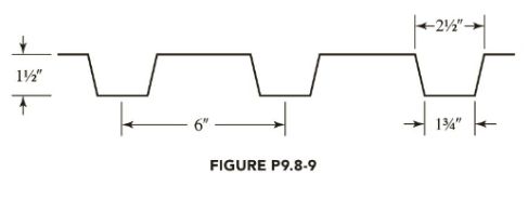
A cross section of the formed steel deck is shown in Figure P9.8-9. The maximum live-load deflection cannot exceed L/360 (use a lower-bound moment of inertia).
a. Use LRFD.
b. User ASD.

Trending nowThis is a popular solution!

Chapter 9 Solutions
STEEL DESIGN (LOOSELEAF)


- Bars AD and CE (E=105 GPa, a = 20.9×10⁻⁶ °C) support a rigid bar ABC carrying a linearly increasing distributed load as shown. The temperature of Bar CE was then raised by 40°C while the temperature of Bar AD remained unchanged. If Bar AD has a cross-sectional area of 200 mm² while CE has 150 mm², determine the following: the normal force in bar AD, the normal force in bar CE, and the vertical displacement at Point A. D 0.4 m -0.8 m A -0.4 m- B -0.8 m- E 0.8 m C 18 kN/marrow_forwardDraw the updated network. Calculate the new project completion date. Check if there are changes to the completion date and/or to the critical path. Mention the causes for such changes, if any. New network based on the new information received after 15 days (Correct calculations, professionally done). Mention if critical path changes or extended. Write causes for change in critical path or extension in the critical path.arrow_forwardThe single degree of freedom system shown in Figure 3 is at its undeformed position. The SDOF system consists of a rigid beam that is massless. The rigid beam has a pinned (i.e., zero moment) connection to the wall (left end) and it supports a mass m on its right end. The rigid beam is supported by two springs. Both springs have the same stiffness k. The first spring is located at distance L/4 from the left support, where L is the length of the rigid beam. The second spring is located at distance L from the left support.arrow_forward
- For the system shown in Figure 2, u(t) and y(t) denote the absolute displacements of Building A and Building B, respectively. The two buildings are connected using a linear viscous damper with damping coefficient c. Due to construction activity, the floor mass of Building B was estimated that vibrates with harmonic displacement that is described by the following function: y(t) = yocos(2πft). Figure 2: Single-degree-of-freedom system in Problem 2. Please compute the following related to Building A: (a) Derive the equation of motion of the mass m. (20 points) (b) Find the expression of the amplitude of the steady-state displacement of the mass m. (10 pointsarrow_forwardAssume a Space Launch System (Figure 1(a)) that is approximated as a cantilever undamped single degree of freedom (SDOF) system with a mass at its free end (Figure 1(b)). The cantilever is assumed to be massless. Assume a wind load that is approximated with a concentrated harmonic forcing function p(t) = posin(ωt) acting on the mass. The known properties of the SDOF and the applied forcing function are given below. • Mass of SDOF: m =120 kip/g • Acceleration of gravity: g = 386 in/sec2 • Bending sectional stiffness of SDOF: EI = 1015 lbf×in2 • Height of SDOF: h = 2000 inches • Amplitude of forcing function: po = 6 kip • Forcing frequency: f = 8 Hzarrow_forwardA study of the ability of individuals to walk in a straight line reported the accompanying data on cadence (strides per second) for a sample of n = 20 randomly selected healthy men. 0.95 0.85 0.92 0.95 0.93 0.85 1.00 0.92 0.85 0.81 0.78 0.93 0.93 1.05 0.93 1.06 1.08 0.96 0.81 0.96 A normal probability plot gives substantial support to the assumption that the population distribution of cadence is approximately normal. A descriptive summary of the data from Minitab follows. Variable cadence Variable N Mean 20 cadence 0.9260 Min 0.7800 Median 0.9300 Max 1.0800 TrMean 0.9256 Q1 0.8500 StDev 0.0832 Q3 0.9600 SEMean 0.0186 (a) Calculate and interpret a 95% confidence interval for population mean cadence. (Round your answers to two decimal places.) strides per second Interpret this interval. ○ with 95% confidence, the value of the true mean cadence of all such men falls inside the confidence interval. With 95% confidence, the value of the true mean cadence of all such men falls above the…arrow_forward
- What is the purchase quantity of 2 x 6 rafters needed for the roof and how many pieces of ridge shingles are needed for the roof? The slope of the roof is 4:12 and the exposure is 5 inches wide. arrow_forwardFor the system shown in Figure 2, u(t) and y(t) denote the absolute displacements of Building A and Building B, respectively. The two buildings are connected using a linear viscous damper with damping coefficient c. Due to construction activity, the floor mass of Building B was estimated that vibrates with harmonic displacement that is described by the following function: y(t) = yocos(2πft). Figure 2: Single-degree-of-freedom system in Problem 2. Please compute the following related to Building A: (a) Derive the equation of motion of the mass m. (20 points) (b) Find the expression of the amplitude of the steady-state displacement of the mass m. (10 pointsarrow_forwardThe direction of the force F_11 is __________LB. The magnitude of the force F_11 is __________LB.arrow_forward
 Steel Design (Activate Learning with these NEW ti...Civil EngineeringISBN:9781337094740Author:Segui, William T.Publisher:Cengage Learning
 Materials Science And Engineering PropertiesCivil EngineeringISBN:9781111988609Author:Charles GilmorePublisher:Cengage Learning
 Construction Materials, Methods and Techniques (M...Civil EngineeringISBN:9781305086272Author:William P. Spence, Eva KultermannPublisher:Cengage Learning
 Traffic and Highway EngineeringCivil EngineeringISBN:9781305156241Author:Garber, Nicholas J.Publisher:Cengage Learning
 Fundamentals Of Construction EstimatingCivil EngineeringISBN:9781337399395Author:Pratt, David J.Publisher:Cengage,
 Architectural Drafting and Design (MindTap Course...Civil EngineeringISBN:9781285165738Author:Alan Jefferis, David A. Madsen, David P. MadsenPublisher:Cengage Learning