
Concept explainers
(a)
Use LFRD method to select the
Answer to Problem 9.5.1P
Explanation of Solution
Given:
Thickness of slab, t = 4.5 inches, spacing = 6.5 ft, span length, L = 36 feet, yield stress = 50 Ksi
Construction load = 20 psf, and live load = 175 psf.
The value of
Concept Used:
Calculation:
Using LRFD method, we have
To select the suitable W 16 shape as follows:
Calculate the loads on the beam as follows:
After curing we have,
Where,
between two adjacent beams.
The dead load on the beam after the concrete has cured is:
Where,
Neglecting the beam weight and check for it later.
Calculate the live load on the beam using the following equation:
Where,
Calculate the factored uniformly distributed load after curing has completed by the following formula:
Where,
Substitute the values, we get
Calculate the bending moment on the beam;
Where,
Let’s try a 16-inch deep beam.
Select a shape with the limiting self-weight given by the following formula:
Where, t is the thickness of the concrete slab, d is the depth of the steel beam, a is the distance of the neutral axis from the top,
Estimating weight per unit foot of the steel beam as:
Let’s try for W 16 X 31 and note the properties and dimensions from the Manual.
Calculate the strength of the section as following below:
Where, the compressive force is C, the compressive force of concrete is
Calculate the compressive force in steel as follows:
Where, the area of steel section is
Get the value of
Calculate the compressive force in concrete as following:
Where, b is the width of the concrete slab, t is the thickness of the concrete beam and
The effective flange width is as follows:
Substitute the values in the above equation, we get
Therefore, the compressive force is as follows:
Therefore, the plastic neutral axis lies in the slab.
Calculate the tensile force (T) and compressive force (C) and the position of plastic neutral axis from the top of concrete slab by following formula:
Compute the flexural strength as:
Where,
neutral axis.
Compute the value of Y as following below:
Substitute the values, we get
Calculate the design strength of the section as follows:
Where,
Substitute the values, we get
The flexural strength of the beam after curing is given as:
Where,
Comparing the values of
Thus, the beam is satisfactory in bending after the curing of concrete is complete.
Check for beam weight.
Where,
Substitute the values, we get
Calculate the maximum bending moment on the beam;
Where,
Check the flexural strength of the beam.
Compare the maximum bending moment and the nominal flexural strength
Comparing the values of
Thus, the section is safe in flexure including its self-weight.
Check for the shear:
Checking the value of nominal value of shear strength of
Where,
The maximum shear force is as following for the above conditions:
Substitute the values, we have
Now comparing the two we have
Therefore, the beam is safe in shear and we can use
Calculate the factored uniformly distributed load after curing has completed by following formula:
Load before curing:
Calculate the self-weight of the slab to be allowed by a single beam as
Where,
The dead load on the beam before the concrete has cured
Where, w is the self-weight of the beam
Substitute the values, we have
Now, calculate the live load on the beam as follows
Where the construction load on the slab is
The uniformly distributed factored load can be found as
Where,
Substitute the values in the above equation, we have
Calculate the maximum bending moment on the beam.
Where,
Check the value of the nominal flexural strength of W- sections from the Manual:
Flexural strength of the beam before curing is given as follows:
Where,
Comparing the values of
Thus, the beam is satisfactory before the curing of concrete is complete.
Therefore, W 16 X 31 is satisfactory to use.
Conclusion:
Therefore,
(b)
Use ASD method to select the
Answer to Problem 9.5.1P
Explanation of Solution
Calculation:
Applying Allowable stress design:
Select appropriate W 16 shape
Calculate the loads on the beam as follows:
Before curing
Calculate the self-weight of the slab to be allowed by a single beam as follows:
Where,
between two adjacent beams.
The dead load on the beam after the concrete has cured is:
Where,
Neglecting the beam weight and check for it later.
Calculate the live load on the beam using the following equation:
Where,
Calculate the allowable uniformly distributed load as follows:
Substitute the values as follows
Calculate the bending moment on the beam;
Where,
Let’s try a 16-inch deep beam.
Select a shape with the limiting self-weight given by the following formula:
Where, t is the thickness of the concrete slab, d is the depth of the steel beam, a is the distance of the neutral axis from the top,
Estimating weight per unit foot of the steel beam as:
Let’s try for W 16 X 31 and note the properties and dimensions from the Manual.
Calculate the strength of the section as following below:
Where, the compressive force is C, the compressive force of concrete is
Calculate the compressive force in steel as follows:
Where, the area of steel section is
Get the value of
Calculate the compressive force in concrete as following:
Where, b is the width of the concrete slab, t is the thickness of the concrete beam and
The effective flange width is as follows;
Substitute the values in the above equation, we get
Therefore, the compressive force is as follows:
Therefore, the plastic neutral axis lies in the slab.
Calculate the tensile force (T) and compressive force (C) and the position of plastic neutral axis from the top of concrete slab by following formula:
Compute the flexural strength as:
Where,
neutral axis.
Compute the value of Y as following below:
Substitute the values, we get
Calculate the design strength of the section as follows:
Where,
Substitute the values, we get
Check the nominal value of the flexural strength of W- sections from the manual.
Where,
Comparing the values, we get
Thus, the beam is satisfactory after curing of concrete has completed.
Check for beam weight
Calculating the max bending mo0ment by busing the following formula:
Substitute the values as follows:
Now, checking the flexural strength with the beam taken into consideration:
Compare the maximum bending moment and the nominal flexural strength
Comparing the values of
Thus, the section is safe in flexure including its self-weight.
Check for the shear:
Checking the value of nominal value of shear strength of
Where,
The maximum shear force is as following for the above conditions:
Substitute the values, we have
Now comparing the two we have
Therefore, the beam is safe in shear.
Loading before curing:
Calculate the self-weight of the slab to be allowed by a single beam as follows:
Where,
between two adjacent beams.
The dead load on the beam before the concrete has cured
Where, w is the self-weight of the beam
Substitute the values, we have
Now, calculate the live load on the beam as follows
Where the construction load on the slab is
The uniformly distributed factored load can be found as
Where,
Substitute the values in the above equation, we have
Calculate the maximum bending moment on the beam;
Where,
Check the value of the nominal flexural strength of W- sections from the Manual:
Flexural strength of the beam before curing is given as follows:
Where,
Comparing the values of
Thus, the beam is satisfactory before the curing of concrete is complete.
Conclusion:
Therefore,
(c)
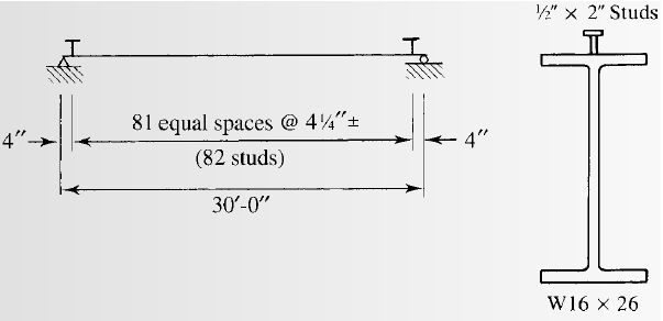
Selecting the stud anchors for the given section.
Answer to Problem 9.5.1P
we will use
Explanation of Solution
Calculation:
We have to check whether the studs satisfy the ASIC specifications.
From AISC specifications the maximum stud diameter will be equal to
Where,
Substitute the values in the equation, we get
Try for,
The area of stud using the following equation as follows:
Where, the diameter of the stud is d.
Substitute
We have the modulus of elasticity of concrete as follows:
Where, the modulus of elasticity of concrete is
unit weight of concrete is
the 28-day compressive strength of concrete is
Substitute
Calculating the shear strength of stud with the following formula:
Substitute the values, we get
Now, the upper limit of the shear strength is as follows:
As, the calculated value is less than the upper limit given by AISC, take the shear strength as:
The number of studs required for the half beam are as follows:
Substitute the values, we have
The number of studs required are as follows:
Substitute the values, we have
Calculate the spacing of the studs as following:
The minimum longitudinal spacing for the studs will be as follows:
Where, the minimum longitudinal spacing for the studs is
Substitute the values, we have
The minimum transversal spacing for the studs will be as follows:
Where, the minimum transversal spacing for the studs is
Substitute the values, we have
The maximum longitudinal spacing for the studs will be as follows:
Where, the maximum longitudinal spacing for the studs is
Substitute the values, we have
Therefore, the upper limit of the spacing is 36 inches.
Calculating the spacing for a stud at each section by the following formula:
Where, S is the spacing required
Conclusion:
Therefore, we will use
Want to see more full solutions like this?
Chapter 9 Solutions
STEEL DESIGN (LOOSELEAF)


- Homework: Determine the proportions of the separate aggregates that will give a gradation within the SCRB wearing coarse specified limits for the aggregates and mix composition for highway pavement asphaltic concrete. The table below shows the results of sieve analysis of samples from the materials available. برو Percent by Weight Passing Sieve Designation Retained on Sieve Designation Coarse Aggregate Fine Aggregate Mineral Filler 3/4 in. (19 mm) 1/2 in. 5 ½ in. (12.5 mm) 3/8 in. 35 ¾ in. (9.5 mm) No. 4 38 No. 4 (4.75 mm) No. 10 17 No. 10 (2 mm) No. 40 5 No. 40 (0.425 mm) No. 80 No. 80 (0.180 mm) No. 200 No. 200 (0.075 mm) Total 18 1118 30 35 5 26 35 60 100 100 100arrow_forwardFor the driven pile shown in figure, estimate the allowable capacity by: (a) Tomlinson a-method, (b)Vijayvergia and Focht A-method. Which one of the two methods are more conservative? Qall =? W.T 18.21 kN/m² 930 L=18m Square pile 27.5cm x 27.5cmarrow_forwardWhat is the vertical deflection at joint C of the truss shown? 75 kN 9 m 7 (3000 mm²) (3000 mm²) (2000 mm²) (3000 mm²) (2000 mm²) 100 kN (3000 mm²) H (3000 mm²) (2000 mm²) (2000 mm²) (3000 mm²)B(3000 mm²) C(3000 mm²)D(3000 mm2)5 a. 9.3 mm↓ b. 9.6 mm↓ c. 8.0 mm ↓ d. 9.1 mm↓ 4 at 6 m = 24 m E = 200 GPa Earrow_forward
- INVERSE FROM POINT A TOWARDS POINT B GIVEN THE FOLLOWINGCOORDINATE VALUES: POINT AN=13,163,953.37'E=3,072,227.10' POINT BN=13,163,463.03'E=3,072,129.30' FIND THE FOLLOWING:DISTANCE FROM A TO BNORTH AZIMUTH (NAZ) FROM A TOWARDS BBEARING OF THE LINE FROM A TOWARDS Barrow_forwardFORWARD FROM POINT B TO POINT A GIVEN THE FOLLOWING: POINT BN=13,163,463.03'E=3,072,129.30' DIRECTION FROM B TO A (NAZ)=276.07529° DISTANCE FROM B TO A = 10.00'arrow_forwardA cheetah is crouched 20 m to the east of an observer. At time t = 0 s, the cheetah begins to run due east toward an antelope that is 50 m to the east of the observer. During the first 2.0 s of the attack, the cheetah's coordinate x varies with time according to the equation x = 20 + 5t?. (a) Find the cheetah's displacement between t1 = 1.0 s and t2 = 2.0 s. (b) Find its average velocity during that interval. (c) Derive an expression for the cheetah's instantaneous velocity as a function of time, and use it to find Vy at t = 1.0 s and t = 2.0 s.arrow_forward
- Write at least 20 words for vocabulary and 10 verbs .for simple present, past, and past participlesarrow_forwardCan you compute the Panel Board Management while using the Lighting and Power Layout Plan as the base for it? The attached Panel Board Management picture is just an example. ps. not graded, I just want to know how to compute it based on a planarrow_forwardMake Sure the attached pic is correct, because the answer in mannings equation is wrong. Can you design a (Open Channel): -Most Efficient Section (Rectangular Shape) -Cost Estimate -Structural Analysis Design Requirements: Bed Slope= 1:1500 Manning's (n)= 0.015 Discharge: Q= 18 m^3/sarrow_forward
- 2-7 The force P applied at joint D of the square frame causes the frame to sway and form the dashed rhombus. Determine the average normal strain developed in wire AC. Assume the three rods are rigid. I understand how you calculate length LAC its just the sqrt(400^2+400^2) = 565.685mm. I do understand that you have to take LAC'-LAC/LAC to get .0258mm/mm. I'm just not understanding the cosine law used to calculate LAC'. I guess what I'm asking is why do you use cos instead of sin or tangent? I've been trying to understand why that was used for a bit now and it's probably something simple I'm forgetting. If you can, please clarify it in detail. Thank you so much!arrow_forwardTraffic flow on a three-lane (one direction) freeway can be described by the Greenshields model. One lane of the three lanes on a section of this freeway will have to be closed to undertake an emergency bridge repair that is expected to take 2 hours. It is estimated that the capacity at the work zone will be reduced by 30 percent of that of the section just upstream of the work zone. The mean free flow speed of the highway is 70 mi/h and the jam density is 150 veh/mi/In. If it is estimated that the demand flow on the highway during the emergency repairs is 85 percent of the capacity, using the deterministic approach, determine the following. (a) the maximum queue length (in veh) that will be formed veh (b) the total delay (in h) h (c) the number of vehicles that will be affected by the incident veh (d) the average individual delay (in min) minarrow_forwardNon-constant sections are used in bridges without changing the appearance of the bridge significantly. Refer to the figure below. Compute the ratio of moment inertial after to before of the plate girder shown (greater than 1). A 10x0.5" steel plate of the same grade as the plate girder and is fillet welded to the flangesarrow_forward
 Steel Design (Activate Learning with these NEW ti...Civil EngineeringISBN:9781337094740Author:Segui, William T.Publisher:Cengage Learning
 Materials Science And Engineering PropertiesCivil EngineeringISBN:9781111988609Author:Charles GilmorePublisher:Cengage Learning
 Architectural Drafting and Design (MindTap Course...Civil EngineeringISBN:9781285165738Author:Alan Jefferis, David A. Madsen, David P. MadsenPublisher:Cengage Learning
 Construction Materials, Methods and Techniques (M...Civil EngineeringISBN:9781305086272Author:William P. Spence, Eva KultermannPublisher:Cengage Learning
 Traffic and Highway EngineeringCivil EngineeringISBN:9781305156241Author:Garber, Nicholas J.Publisher:Cengage Learning
 Fundamentals Of Construction EstimatingCivil EngineeringISBN:9781337399395Author:Pratt, David J.Publisher:Cengage,