
Concept explainers
Videos
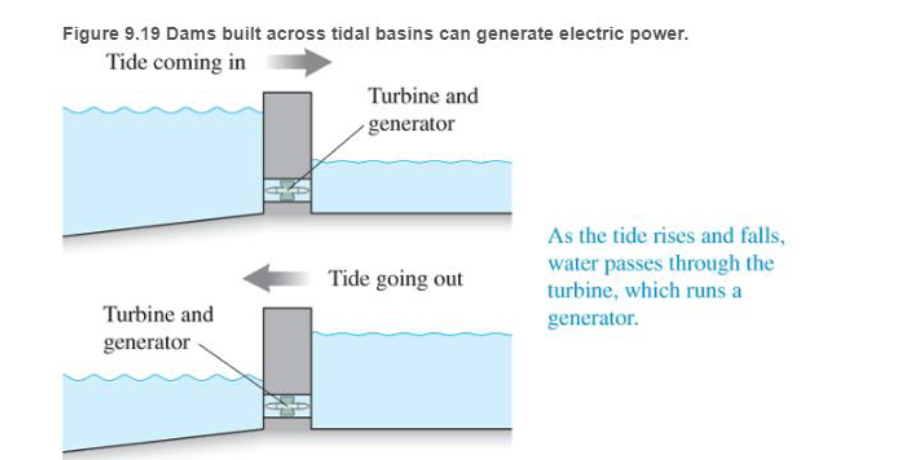
Tidal energy Tides are now used so gene-ate electric power in two ways. In the first, huge dams can be built. across the mouth of a river where it exits to the ocean. As the ocean tide moves in and out of this tidal bas in or estuary, the water flows through tunnels in the dam (see Figure 9.19). This flowing water turns turbines in the tunnels that run electric generators. Unfortunately, this technique works best with large increases in tides—a 5-m difference between high and low tide Such differences are found at only a small number of places Currently, France is the only country that successfully uses this power source A tidal basin plant in France, the Rance. Tidal Power Station. makes 240 megawatts of power—enough energy to power 240,000 homes. Damming tidal basins can have negative environmental effects because of reduced tidal flow and silt buildup. Another disadvantage is that they can only generate electricity when the tide is flowing in or out, for about 10 hours each day.
A second method for collecting energy from the tidal flow (as well as all water flow) is to place turbines directly in the water—like windmills in moving water instead of in moving air. These water turbines have the advantages that they are much cheaper to build, they do not have the environmental problems of a tidal basin, and there are many more suitable sites for such water flow energy farms. Also the energy density of flowing water is about 800 times the energy density of dry air flow. Verdant Power is developing turbine prototypes in the East River near New York City and in the Saint Lawrence Seaway in Canada, and they are looking at other sites in the Puget Sound and all over the world. The worldwide potential tor hydroelectric power is about
The Rance tidal basin can only produce electricity when what is occurring?
a. Water is moving into the estuary from the ocean.
b. Water is moving into the ocean from the estuary.
c. Water is moving in either direction. d. The Moon is full.
e. The Moon is full and directly overhead.
Want to see the full answer?
Check out a sample textbook solution
Chapter 9 Solutions
College Physics
Additional Science Textbook Solutions
Chemistry: An Introduction to General, Organic, and Biological Chemistry (13th Edition)
Microbiology with Diseases by Body System (5th Edition)
Genetic Analysis: An Integrated Approach (3rd Edition)
Chemistry & Chemical Reactivity
Microbiology: An Introduction
Human Physiology: An Integrated Approach (8th Edition)


- A planar double pendulum consists of two point masses \[m_1 = 1.00~\mathrm{kg}, \qquad m_2 = 1.00~\mathrm{kg}\]connected by massless, rigid rods of lengths \[L_1 = 1.00~\mathrm{m}, \qquad L_2 = 1.20~\mathrm{m}.\]The upper rod is hinged to a fixed pivot; gravity acts vertically downward with\[g = 9.81~\mathrm{m\,s^{-2}}.\]Define the generalized coordinates \(\theta_1,\theta_2\) as the angles each rod makes with thedownward vertical (positive anticlockwise, measured in radians unless stated otherwise).At \(t=0\) the system is released from rest with \[\theta_1(0)=120^{\circ}, \qquad\theta_2(0)=-10^{\circ}, \qquad\dot{\theta}_1(0)=\dot{\theta}_2(0)=0 .\]Using the exact nonlinear equations of motion (no small-angle or planar-pendulumapproximations) and assuming the rods never stretch or slip, determine the angle\(\theta_2\) at the instant\[t = 10.0~\mathrm{s}.\]Give the result in degrees, in the interval \((-180^{\circ},180^{\circ}]\).arrow_forwardWhat are the expected readings of the ammeter and voltmeter for the circuit in the figure below? (R = 5.60 Ω, ΔV = 6.30 V) ammeter I =arrow_forwardsimple diagram to illustrate the setup for each law- coulombs law and biot savart lawarrow_forward
- A circular coil with 100 turns and a radius of 0.05 m is placed in a magnetic field that changes at auniform rate from 0.2 T to 0.8 T in 0.1 seconds. The plane of the coil is perpendicular to the field.• Calculate the induced electric field in the coil.• Calculate the current density in the coil given its conductivity σ.arrow_forwardAn L-C circuit has an inductance of 0.410 H and a capacitance of 0.250 nF . During the current oscillations, the maximum current in the inductor is 1.80 A . What is the maximum energy Emax stored in the capacitor at any time during the current oscillations? How many times per second does the capacitor contain the amount of energy found in part A? Please show all steps.arrow_forwardA long, straight wire carries a current of 10 A along what we’ll define to the be x-axis. A square loopin the x-y plane with side length 0.1 m is placed near the wire such that its closest side is parallel tothe wire and 0.05 m away.• Calculate the magnetic flux through the loop using Ampere’s law.arrow_forward
- Describe the motion of a charged particle entering a uniform magnetic field at an angle to the fieldlines. Include a diagram showing the velocity vector, magnetic field lines, and the path of the particle.arrow_forwardDiscuss the differences between the Biot-Savart law and Coulomb’s law in terms of their applicationsand the physical quantities they describe.arrow_forwardExplain why Ampere’s law can be used to find the magnetic field inside a solenoid but not outside.arrow_forward
- 3. An Atwood machine consists of two masses, mA and m B, which are connected by an inelastic cord of negligible mass that passes over a pulley. If the pulley has radius RO and moment of inertia I about its axle, determine the acceleration of the masses mA and m B, and compare to the situation where the moment of inertia of the pulley is ignored. Ignore friction at the axle O. Use angular momentum and torque in this solutionarrow_forwardA 0.850-m-long metal bar is pulled to the right at a steady 5.0 m/s perpendicular to a uniform, 0.650-T magnetic field. The bar rides on parallel metal rails connected through a 25-Ω, resistor (Figure 1), so the apparatus makes a complete circuit. Ignore the resistance of the bar and the rails. Please explain how to find the direction of the induced current.arrow_forwardFor each of the actions depicted, determine the direction (right, left, or zero) of the current induced to flow through the resistor in the circuit containing the secondary coil. The coils are wrapped around a plastic core. Immediately after the switch is closed, as shown in the figure, (Figure 1) in which direction does the current flow through the resistor? If the switch is then opened, as shown in the figure, in which direction does the current flow through the resistor? I have the answers to the question, but would like to understand the logic behind the answers. Please show steps.arrow_forward
 Physics for Scientists and Engineers: Foundations...PhysicsISBN:9781133939146Author:Katz, Debora M.Publisher:Cengage Learning
 College PhysicsPhysicsISBN:9781285737027Author:Raymond A. Serway, Chris VuillePublisher:Cengage Learning
 Principles of Physics: A Calculus-Based TextPhysicsISBN:9781133104261Author:Raymond A. Serway, John W. JewettPublisher:Cengage Learning
 Physics for Scientists and Engineers with Modern ...PhysicsISBN:9781337553292Author:Raymond A. Serway, John W. JewettPublisher:Cengage Learning
 Physics for Scientists and EngineersPhysicsISBN:9781337553278Author:Raymond A. Serway, John W. JewettPublisher:Cengage Learning