
Concept explainers
Videos
8.121 and 8.123 A cable is placed around three parallel pipes. Two of the pipes are fixed and do not rotate; the third pipe is slowly rotated. Knowing that the coefficients of friction are μS = 0.25 and μk = 0.20, determine the largest weight W that can be raised (a) if only pipe A is rotated counterclockwise, (b) if only pipe C is rotated clockwise.
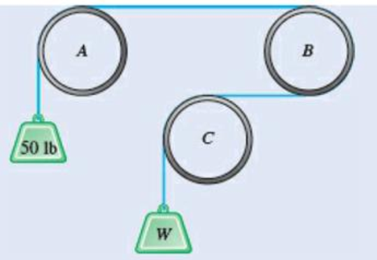
Fig. P8.120 and P8.121
(a)
Find the largest weight W that can be raised only when the pipe A is rotated counter clockwise.
Answer to Problem 8.121P
The largest weight W that can be raised only when the pipe A is rotated counter clockwise is
Explanation of Solution
Given information:
The coefficient of static friction is
The coefficient of kinetic friction is
Calculation:
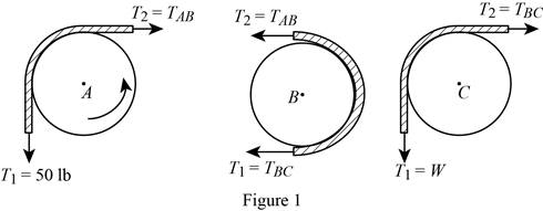
Show the free-body diagram of the pipes A, B, and C as in Figure 1.
Find the angle of the cable wounded around the pipe as follows;
Find the largest weight W using the equation.
Substitute 0.25 for
Therefore, the largest weight W that can be raised only when the pipe A is rotated counter clockwise is
(b)
Find the largest weight W that can be raised only when the pipe C is rotated clockwise.
Answer to Problem 8.121P
The largest weight W that can be raised only when the pipe C is rotated clockwise is
Explanation of Solution
Given information:
The coefficient of static friction is
The coefficient of kinetic friction is
Calculation:
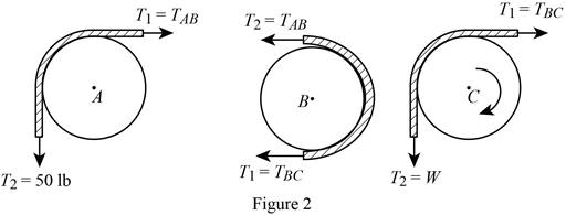
Show the free-body diagram of the pipes A, B, and C as in Figure 2.
Find the angle of the cable wounded around the pipe as follows;
Find the largest weight W using the equation.
Substitute 0.25 for
Therefore, the largest weight W that can be raised only when the pipe C is rotated clockwise is
Want to see more full solutions like this?
Chapter 8 Solutions
VECTOR MECHANIC


- Assume a Space Launch System (Figure 1(a)) that is approximated as a cantilever undamped single degree of freedom (SDOF) system with a mass at its free end (Figure 1(b)). The cantilever is assumed to be massless. Assume a wind load that is approximated with a concentrated harmonic forcing function p(t) = posin(ωt) acting on the mass. The known properties of the SDOF and the applied forcing function are given below. • Mass of SDOF: m =120 kip/g • Acceleration of gravity: g = 386 in/sec2 • Bending sectional stiffness of SDOF: EI = 1015 lbf×in2 • Height of SDOF: h = 2000 inches • Amplitude of forcing function: po = 6 kip • Forcing frequency: f = 8 Hz Figure 1: Single-degree-of-freedom system in Problem 1. Please compute the following considering the steady-state response of the SDOF system. Do not consider the transient response unless it is explicitly stated in the question. (a) The natural circular frequency and the natural period of the SDOF. (10 points) (b) The maximum displacement of…arrow_forwardAssume a Space Launch System (Figure 1(a)) that is approximated as a cantilever undamped single degree of freedom (SDOF) system with a mass at its free end (Figure 1(b)). The cantilever is assumed to be massless. Assume a wind load that is approximated with a concentrated harmonic forcing function p(t) = posin(ωt) acting on the mass. The known properties of the SDOF and the applied forcing function are given below. • Mass of SDOF: m =120 kip/g • Acceleration of gravity: g = 386 in/sec2 • Bending sectional stiffness of SDOF: EI = 1015 lbf×in2 • Height of SDOF: h = 2000 inches • Amplitude of forcing function: po = 6 kip • Forcing frequency: f = 8 Hz Figure 1: Single-degree-of-freedom system in Problem 1. Please compute the following considering the steady-state response of the SDOF system. Do not consider the transient response unless it is explicitly stated in the question. (a) The natural circular frequency and the natural period of the SDOF. (10 points) (b) The maximum displacement of…arrow_forwardPlease solve 13 * √(2675.16)² + (63.72 + 2255,03)² = 175x106 can you explain the process for getting d seperate thank youarrow_forward
- If the 300-kg drum has a center of mass at point G, determine the horizontal and vertical components of force acting at pin A and the reactions on the smooth pads C and D. The grip at B on member DAB resists both horizontal and vertical components of force at the rim of the drum. P 60 mm; 60 mm: 600 mm A E 30° B C 390 mm 100 mm D Garrow_forwardThe design of the gear-and-shaft system shown requires that steel shafts of the same diameter be used for both AB and CD. It is further required that the angle D through which end D of shaft CD rotates not exceed 1.5°. Knowing that G = 77.2 GPa, determine the required diameter of the shafts. 40 mm 400 mm 100 mm 600 mm T-1000 N-m Darrow_forwardAssume a Space Launch System (Figure 1(a)) that is approximated as a cantilever undamped single degree of freedom (SDOF) system with a mass at its free end (Figure 1(b)). The cantilever is assumed to be massless. Assume a wind load that is approximated with a concentrated harmonic forcing function p(t) = posin(ωt) acting on the mass. The known properties of the SDOF and the applied forcing function are given below. • Mass of SDOF: m =120 kip/g • Acceleration of gravity: g = 386 in/sec2 • Bending sectional stiffness of SDOF: EI = 1015 lbf×in2 • Height of SDOF: h = 2000 inches • Amplitude of forcing function: po = 6 kip • Forcing frequency: f = 8 Hzarrow_forward
- 13.44 The end of a cylindrical liquid cryogenic propellant tank in free space is to be protected from external (solar) radiation by placing a thin metallic shield in front of the tank. Assume the view factor Fts between the tank and the shield is unity; all surfaces are diffuse and gray, and the surroundings are at 0 K. Tank T₁ Shield, T T₁ = 100 K E1 Solar irradiation Gs ε₁ = ε₂ = 0.05 ε₁ = 0.10 Gs = 1250 W/m² E2 Find the temperature of the shield T, and the heat flux (W/m²) to the end of the tank.arrow_forwardquestion 664 thank youarrow_forward13.38 Consider the attic of a home located in a hot climate. The floor of the attic is characterized by a width of L₁ = 8 m while the roof makes an angle of 0 = 30° from the horizontal direction, as shown in the schematic. The homeowner wishes to reduce the heat load to the home by adhering bright aluminum foil (ε = 0.07) onto the surfaces of the attic space. Prior to installation of the foil, the surfaces are of emissivity & = 0.90. Attic A2, 82, T2 0 = 30° A1, E1, T₁ 土 L₁ = 8 m (a) Consider installation on the bottom of the attic roof only. Determine the ratio of the radiation heat transfer after to before the installation of the foil. (b) Determine the ratio of the radiation heat transfer after to before installation if the foil is installed only on the top of the attic floor. (c) Determine the ratio of the radiation heat transfer if the foil is installed on both the roof bottom and the floor top.arrow_forward
- 13.1 Determine F2 and F2 for the following configura- tions using the reciprocity theorem and other basic shape factor relations. Do not use tables or charts. (a) Small sphere of area A, under a concentric hemi- sphere of area A₂ = 3A₁ A₂ A1 (a) (b) Long duct. Also, what is F₁₂? A₂ Αν (b) (c) Long inclined plates (point B is directly above the center of A₁) B 100 mm A₂ - 220 mm (c) (d) Long cylinder lying on infinite plane + A₁ Az (d) (e) Hemisphere-disk arrangement -A₂, hemisphere, diameter D A₂ A₁, disk, diameter D/2 (e) (f) Long, open channel 1 m AA₂ 2 m (f) (g) Long cylinders with A₁ = 4A₁. Also, what is F₁₂? -D₁ A1 -A₂ -D2 (e) (h) Long, square rod in a long cylinder. Also, what is F22? w=D/5 18 A₁ -A2 (h) -Darrow_forward13.9 Determine the shape factor, F12, for the rectangles shown. 6 m 1 3 m 6 m 1 m 2 6 m 1 0.5 m 2 1 m (a) Perpendicular rectangles without a common edge. -1 m. (b) Parallel rectangles of unequal areas.arrow_forwardI keep getting the wrong answer i have gotten 6519.87 and 319.71arrow_forward
 Elements Of ElectromagneticsMechanical EngineeringISBN:9780190698614Author:Sadiku, Matthew N. O.Publisher:Oxford University Press
 Mechanics of Materials (10th Edition)Mechanical EngineeringISBN:9780134319650Author:Russell C. HibbelerPublisher:PEARSON
 Thermodynamics: An Engineering ApproachMechanical EngineeringISBN:9781259822674Author:Yunus A. Cengel Dr., Michael A. BolesPublisher:McGraw-Hill Education
 Control Systems EngineeringMechanical EngineeringISBN:9781118170519Author:Norman S. NisePublisher:WILEY
 Mechanics of Materials (MindTap Course List)Mechanical EngineeringISBN:9781337093347Author:Barry J. Goodno, James M. GerePublisher:Cengage Learning
 Engineering Mechanics: StaticsMechanical EngineeringISBN:9781118807330Author:James L. Meriam, L. G. Kraige, J. N. BoltonPublisher:WILEY