
Videos
A 15° wedge is forced under a 50-kg pipe as shown. The coefficient of static friction at all surfaces is 0.20. (a) Show that slipping will occur between the pipe and the vertical wall. (b) Determine the force P required to move the wedge.
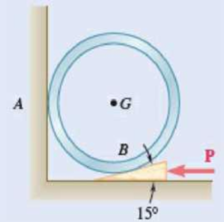
Fig. P8.64 and P8.65
(a)
Show that the slipping will occur between the pipe and the vertical wall.
Explanation of Solution
Given information:
The mass of the pipe is
The value of angle
The coefficient of static friction at all surfaces is
Calculation:
Find the weight (W) of the pipe using the relation.
Here, the acceleration due to gravity is g.
Consider the acceleration due to gravity is
Substitute 50 kg for m and
Show the free-body diagram of the pipe as in Figure 1.
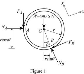
Find the friction force at point A using the relation.
Here, the normal force at point A is
Find the normal force at point A by taking moment about point B.
Substitute 490.5 N for W, 0.20 for
Find the friction force at point B
Substitute 490.5 N for W, 0.20 for
Find the normal force at point B
Substitute 490.5 N for W, 0.20 for
Find the maximum friction force at point B using the relation.
Substitute 0.20 for
The friction force at point B is less than the maximum friction force at point B.
Therefore, the slipping will not occur at point B and the slipping will occur between the pipe and the vertical wall.
(b)
Find the force P required to move the wedge.
Answer to Problem 8.64P
The force P required to move the wedge is
Explanation of Solution
Given information:
The mass of the pipe is
The value of angle
The coefficient of static friction at all surfaces is
Calculation:
Show the free-body diagram of the wedge as in Figure 2.
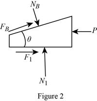
Find the normal force
Substitute 554.155 N for
Find the force P by resolving the horizontal component of forces.
Substitute 554.155 N for
Therefore, the force P required to move the wedge is
Want to see more full solutions like this?
Chapter 8 Solutions
VECTOR MECHANIC


- B1 Please help on the attached question.arrow_forwardQu 4 A cylindrical metal specimen 15.0 mm in diameter and 150 mm long is to be subjected to a tensile stress of 50 MPa; at this stress level, the resulting deformation will be totally elastic. If the elongation must be less than 0.072 mm, which of the metals in Table 1 are suitable candidates? If, in addition, the maximum permissible diameter decrease is 2.3 × 10⁻³ mm when the tensile stress of 50 MPa is applied, which of the metals that satisfy the criterion in part (a) are suitable candidates? see on the tables given part a and b i need to show all work problems formula step by step please make sure is correctly material sciencearrow_forwardZ4 please help on the attached question.arrow_forward
- From dynamics CHAPTER 12: Rectilinear Kinematics. Continuous Motion. Qu. 1 The velocity of a particle traveling along a straight line is v = (3t2 - 6t)ft/s, where t is in seconds. If s = 4ft when t = 0, determine the position of the particle when t = 4s. What is the total distance traveled during the time interval t = 0 to t = 4s? Also, what is the acceleration when t = 2 s?I want to show all work step by step problemsarrow_forwardZ1 please help on the attached question.arrow_forwardProblem 3 (10 pts). When using linear shape functions to solve the multiphysics thermoelastic problem considered in class, we found that the stress in the rod is affected by unphysical oscillations like the following plot(a) [10pts] What is the origin of this issue and how can we fix it?arrow_forward
 International Edition---engineering Mechanics: St...Mechanical EngineeringISBN:9781305501607Author:Andrew Pytel And Jaan KiusalaasPublisher:CENGAGE L