
Concept explainers
Videos
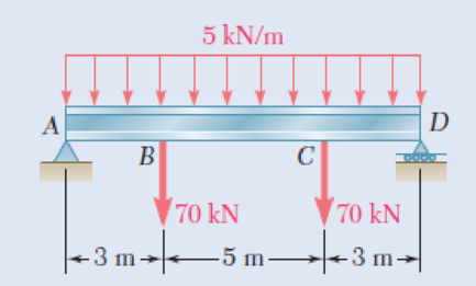
8.9 through 8.14 Each of the following problems refers to a rolled-steel shape selected in a problem of Chap. 5 to support a given loading at a minimal cost while satisfying the requirement σm ≤ σall. For the selected design, determine (a) the actual value of σm in the beam, (b) the maximum value of the principal stress σmax at the junction of a flange and the web.
8.9 Loading of Prob. 5.73 and selected W530 × 92 shape.
Fig. P5.73
(a)
The actual value of
Answer to Problem 9P
The actual value of
Explanation of Solution
Given information:
Refer to problem 5.73 in chapter 5 in the textbook.
The shape of the rolled steel section is
Calculation:
Show the free-body diagram of the beam as in Figure 1.
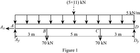
Determine the vertical reaction at point D by taking moment at point A.
Determine the vertical reaction at point A by resolving the vertical component of forces.
Shear force:
Show the calculation of shear force as follows;
Show the calculated shear force values as in Table 1.
| Location (x) m | Shear force (V) kN |
| A | 97.5 |
| B (Left) | 82.5 |
| B (Right) | 12.5 |
| C (Left) | –12.5 |
| C (Right) | –82.5 |
| D | –97.5 |
Plot the shear force diagram as in Figure 2.
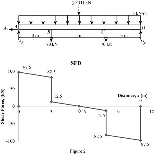
Location of the maximum bending moment:
The maximum bending moment occurs where the shear force changes sign.
Refer to Figure 2;
Use the method of similar triangle.
The maximum bending moment occurs at a distance 5.5 m from the left end of the beam.
Bending moment:
Show the calculation of the bending moment as follows;
Show the calculated bending moment values as in Table 2.
| Location (x) m | Bending moment (M) kN-m |
| A | 0 |
| B | 270 |
| Max BM | 285.625 |
| C | 270 |
| D | 0 |
Plot the bending moment diagram as in Figure 3.
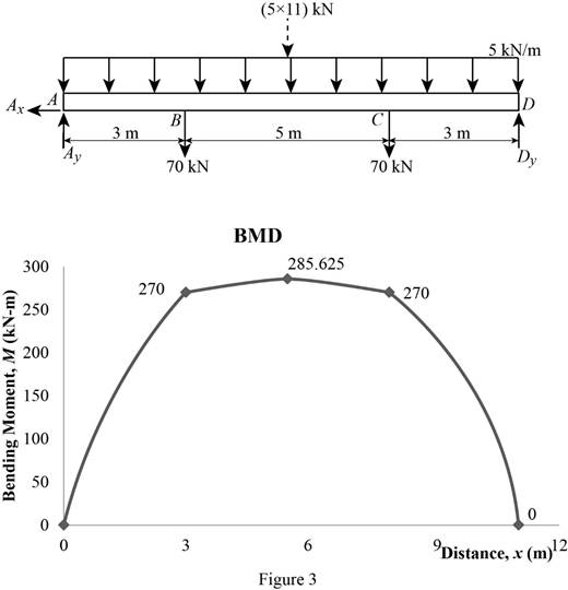
Refer to the Figure 3;
The maximum bending moment in the beam is
Write the section a property for a
| Dimension | Unit( |
| d | 533 mm |
| 209 mm | |
| 15.6 mm | |
| I | |
Here, d is depth of the section,
Find the value of C using the relation:
Substitute
Find the maximum value of normal stress
Here,
Substitute
Thus, the actual value of
(b)
The maximum value of principal stress
Answer to Problem 9P
The maximum value of principal stress
Explanation of Solution
Calculation:
Find the value
Here, c is the centroid and
Substitute
Find the area of flange
Here,
Substitute
Find the centroid of flange
Substitute
Find the first moment about neutral axis
Here,
Substitute
At mid span the value of
Find the maximum value of principal stress
Here, actual value of normal stress
Substitute
At section B and C.
Find the maximum value of normal stress
Here,
Substitute
Find the value of
Substitute
Find the shear stress at b
Substitute
Substitute
Find the maximum shearing stress (R) using the relation:
Here,
Substitute
Determine the maximum value of the principle stress using the relation:
Here, R is the maximum shearing stress and
Substitute
Based on results,
Select the maximum value of principal stress
The maximum value of principal stress
Want to see more full solutions like this?
Chapter 8 Solutions
EBK MECHANICS OF MATERIALS


- Problem 6. The circular plate shown rotates about its vertical diameter. At the instant shown, the angular velocity ₁ of the plate is 10 rad/s and is decreasing at the rate of 25 rad/s². The disk lies in the XY plane and Point D of strap CD moves upward. The relative speed u of Point D of strap CD is 1.5 m/s and is decreasing at the rate of 3 m/s². Determine (a) the velocity of D, (b) the acceleration of D. Answers: =0.75 +1.299]-1.732k m/s a=-28.6 +3.03-10.67k m/s² 200 mm x Zarrow_forwardProblem 1. The flywheel A has an angular velocity o 5 rad/s. Link AB is connected via ball and socket joints to the flywheel at A and a slider at B. Find the angular velocity of link AB and the velocity of slider B at this instant. (Partial Answer: @ABN = -2î + 2.25; red Z -1.2 ft C -7 Y -1.5 ft- B 2.0 ftarrow_forwardNeed help pleasearrow_forward
- PROBLEM 15.225 The bent rod shown rotates at the constant rate @₁ = 5 rad/s and collar C moves toward point B at a constant relative speed u = 39 in./s. Knowing that collar C is halfway between points B and D at the instant shown, determine its velocity and acceleration. Answers: v=-45 +36.6)-31.2 k in./s āc = -2911-270} in./s² 6 in 20.8 in. 14.4 in.arrow_forwardNeed help, please show all work, steps, units and please box out and round answers to 3 significant figures. Thank you!..arrow_forwardNeed help, please show all work, steps, units and please box out and round answers to 3 significant figures. Thank you!...arrow_forward
- FL y b C Z Determine the moment about O due to the force F shown, the magnitude of the force F = 76.0 lbs. Note: Pay attention to the axis. Values for dimensions on the figure are given in the following table. Note the figure may not be to scale. Variable Value a 1.90 ft b 2.80 ft с 2.60 ft d 2.30 ft Mo 144 ft-lb = -212 × 1 + xk) ☑+212arrow_forward20 in. PROBLEM 15.206 Rod AB is connected by ball-and-socket joints to collar A and to the 16-in.-diameter disk C. Knowing that disk C rotates counterclockwise at the constant rate ₁ =3 rad/s in the zx plane, determine the velocity of collar A for the position shown. 25 in. B 8 in. Answer: -30 in/s =arrow_forwardB Z 001 2.5 ft PROBLEM 15.236 The arm AB of length 16 ft is used to provide an elevated platform for construction workers. In the position shown, arm AB is being raised at the constant rate de/dt = 0.25 rad/s; simultaneously, the unit is being rotated about the Y axis at the constant rate ₁ =0.15 rad/s. Knowing that 20°, determine the velocity and acceleration of Point B. Answers: 1.371 +3.76)+1.88k ft/s a=1.22 -0.342)-0.410k ft/s² Xarrow_forward
- F1 3 5 4 P F2 F2 Ꮎ Ꮎ b P 3 4 5 F1 The electric pole is subject to the forces shown. Force F1 245 N and force F2 = 310 N with an angle = 20.2°. Determine the moment about point P of all forces. Take counterclockwise moments to be positive. = Values for dimensions on the figure are given in the following table. Note the figure may not be to scale. Variable Value a 2.50 m b 11.3 m C 13.0 m The moment about point P is 3,414 m. × N- If the moment about point P sums up to be zero. Determine the distance c while all other values remained the same. 1.26 m.arrow_forwardZ 0.2 m B PROBLEM 15.224 Rod AB is welded to the 0.3-m-radius plate, which rotates at the constant rate ₁ = 6 rad/s. Knowing that collar D moves toward end B of the rod at a constant speed u = 1.3 m, determine, for the position shown, (a) the velocity of D, (b) the acceleration of D. Answers: 1.2 +0.5-1.2k m/s a=-7.21-14.4k m/s² A 0.25 m 0.3 marrow_forwardI am trying to code in MATLAB the equations of motion for malankovich orbitlal elements. But, I am having a problem with the B matrix. Since f matrix is 7x1 and a_d matrix has to be 3x1, the B matrix has to be 7x3. I don't know how that is possible. Can you break down the B matrix for me and let me know what size it is?arrow_forward
 Elements Of ElectromagneticsMechanical EngineeringISBN:9780190698614Author:Sadiku, Matthew N. O.Publisher:Oxford University Press
 Mechanics of Materials (10th Edition)Mechanical EngineeringISBN:9780134319650Author:Russell C. HibbelerPublisher:PEARSON
 Thermodynamics: An Engineering ApproachMechanical EngineeringISBN:9781259822674Author:Yunus A. Cengel Dr., Michael A. BolesPublisher:McGraw-Hill Education
 Control Systems EngineeringMechanical EngineeringISBN:9781118170519Author:Norman S. NisePublisher:WILEY
 Mechanics of Materials (MindTap Course List)Mechanical EngineeringISBN:9781337093347Author:Barry J. Goodno, James M. GerePublisher:Cengage Learning
 Engineering Mechanics: StaticsMechanical EngineeringISBN:9781118807330Author:James L. Meriam, L. G. Kraige, J. N. BoltonPublisher:WILEY