
Concept explainers
Videos
8.9 through 8.14 Each of the following problems refers to a rolled-steel shape selected in a problem of Chap. 5 to support a given loading at a minimal cost while satisfying the requirement σm ≤ σall. For the selected design, determine (a) the actual value of σm in the beam, (b) the maximum value of the principal stress σmax at the junction of a flange and the web.
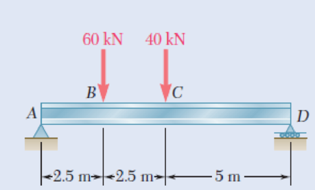
8.14 Loading of Prob. 5.78 and selected S460 × 81.4 shape.
Fig. P5.78
(a)
The actual value of
Answer to Problem 14P
The actual value of
Explanation of Solution
Given information:
Refer to problem 5.78 in chapter 5 in the textbook.
The allowable normal stress of the beam is
Calculation:
Design of beam:
Show the free-body diagram of the beam as in Figure 1.
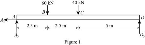
Determine the vertical reaction at point D by taking moment at point A.
Determine the vertical reaction at point A by resolving the vertical component of forces.
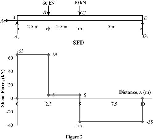
Shear force:
Show the calculation of shear force as follows;
Show the calculated shear force values as in Table 1.
| Location (x) m | Shear force (V) kN |
| A | 65 |
| B (Left) | 65 |
| B (Right) | 5 |
| C (Left) | 5 |
| C (Right) | –35 |
| D | –35 |
Plot the shear force diagram as in Figure 2.
Bending moment:
Show the calculation of the bending moment as follows;
Show the calculated bending moment values as in Table 2.
| Location (x) m | Bending moment (M) kN-m |
| A | 0 |
| B | 162.5 |
| C | 175 |
| D | 0 |
Plot the bending moment diagram as in Figure 3.
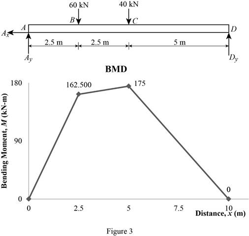
Refer to the Figure 3;
The maximum bending moment in the beam is
Write the section a property for a
| Dimension | Unit( |
| d | 457 |
| 152 | |
| 17.6 | |
Here, d is depth of the section,
Find the value of C using the relation:
Substitute
Find the maximum value of normal stress
Here,
Substitute
Thus, the actual value of
(b)
The maximum value of principal stress
Answer to Problem 14P
The maximum value of principal stress
Explanation of Solution
Calculation:
Find the value
Here, c is the centroid and
Substitute
Find the area of flange
Here,
Substitute
Find the centroid of flange
Substitute
Find the first moment about neutral axis
Here,
Substitute
At section C,
Find the value of
Here, actual value of normal stress
Substitute
Find the shear stress at
Modify Equation (8).
Substitute
Find the maximum shearing stress (R) using the relation:
Here,
Substitute
Determine the maximum value of the principle stress using the relation:
Here, R is the maximum shearing stress and
Substitute
At section B,
Find the maximum value of normal stress
Here,
Substitute
Find the value of
Substitute
Find the shear stress at b
Substitute
Refer to figure 3.
Substitute
Find the maximum shearing stress (R) using the relation:
Here,
Substitute
Determine the maximum value of the principle stress using the relation:
Here, R is the maximum shearing stress and
Substitute
Based on results,
Select the maximum value of principal stress
Thus, the maximum value of principal stress
Want to see more full solutions like this?
Chapter 8 Solutions
EBK MECHANICS OF MATERIALS
Additional Engineering Textbook Solutions
Vector Mechanics For Engineers
Database Concepts (8th Edition)
Electric Circuits. (11th Edition)
Mechanics of Materials (10th Edition)
Thermodynamics: An Engineering Approach
Automotive Technology: Principles, Diagnosis, And Service (6th Edition) (halderman Automotive Series)


- CORRECT AND DETAILED SOLUTION WITH FBD ONLY. I WILL UPVOTE THANK YOU. CORRECT ANSWER IS ALREADY PROVIDED. I REALLY NEED FBD. The roof truss shown carries roof loads, where P = 10 kN. The truss is consisting of circular arcs top andbottom chords with radii R + h and R, respectively.Given: h = 1.2 m, R = 10 m, s = 2 m.Allowable member stresses:Tension = 250 MPaCompression = 180 MPa1. If member KL has square section, determine the minimum dimension (mm).2. If member KL has circular section, determine the minimum diameter (mm).3. If member GH has circular section, determine the minimum diameter (mm).ANSWERS: (1) 31.73 mm; (2) 35.81 mm; (3) 18.49 mmarrow_forwardPROBLEM 3.23 3.23 Under normal operating condi- tions a motor exerts a torque of magnitude TF at F. The shafts are made of a steel for which the allowable shearing stress is 82 MPa and have diameters of dCDE=24 mm and dFGH = 20 mm. Knowing that rp = 165 mm and rg114 mm, deter- mine the largest torque TF which may be exerted at F. TF F rG- rp B CH TE Earrow_forward1. (16%) (a) If a ductile material fails under pure torsion, please explain the failure mode and describe the observed plane of failure. (b) Suppose a prismatic beam is subjected to equal and opposite couples as shown in Fig. 1. Please sketch the deformation and the stress distribution of the cross section. M M Fig. 1 (c) Describe the definition of the neutral axis. (d) Describe the definition of the modular ratio.arrow_forward
- using the theorem of three moments, find all the moments, I only need concise calculations with minimal explanations. The correct answers are provided at the bottomarrow_forwardMechanics of materialsarrow_forwardusing the theorem of three moments, find all the moments, I need concise calculations onlyarrow_forward
- Can you provide steps and an explaination on how the height value to calculate the Pressure at point B is (-5-3.5) and the solution is 86.4kPa.arrow_forwardPROBLEM 3.46 The solid cylindrical rod BC of length L = 600 mm is attached to the rigid lever AB of length a = 380 mm and to the support at C. When a 500 N force P is applied at A, design specifications require that the displacement of A not exceed 25 mm when a 500 N force P is applied at A For the material indicated determine the required diameter of the rod. Aluminium: Tall = 65 MPa, G = 27 GPa. Aarrow_forwardFind the equivalent mass of the rocker arm assembly with respect to the x coordinate. k₁ mi m2 k₁arrow_forward
 Elements Of ElectromagneticsMechanical EngineeringISBN:9780190698614Author:Sadiku, Matthew N. O.Publisher:Oxford University Press
 Mechanics of Materials (10th Edition)Mechanical EngineeringISBN:9780134319650Author:Russell C. HibbelerPublisher:PEARSON
 Thermodynamics: An Engineering ApproachMechanical EngineeringISBN:9781259822674Author:Yunus A. Cengel Dr., Michael A. BolesPublisher:McGraw-Hill Education
 Control Systems EngineeringMechanical EngineeringISBN:9781118170519Author:Norman S. NisePublisher:WILEY
 Mechanics of Materials (MindTap Course List)Mechanical EngineeringISBN:9781337093347Author:Barry J. Goodno, James M. GerePublisher:Cengage Learning
 Engineering Mechanics: StaticsMechanical EngineeringISBN:9781118807330Author:James L. Meriam, L. G. Kraige, J. N. BoltonPublisher:WILEY